Hand held magnetic induction thermography system

a magnetic induction and thermography technology, applied in the field of non-destructive evaluation of articles of manufacture, can solve the problems of unfavorable speed, flexibility, and/or potential contamination of articles tested, and the structural features and flaws of objects that generate localized heat under such stimulation, and achieve the effects of reducing the risk of eddy current contamination, speed and flexibility

Inactive Publication Date: 2009-02-03
SIEMENS ENERGY INC
View PDF26 Cites 31 Cited by
  • Summary
  • Abstract
  • Description
  • Claims
  • Application Information

AI Technical Summary

Benefits of technology

[0012]Placing a transformer 15 in the handle 16 reduces current in the cable 30 that would otherwise be needed between the generator 10 and the handle 16. This reduces resistive heating in the cable 30, which avoids damage to the cable 30. The current and transformer parameters above are provided as examples only. The generator 10 may provide current with user-selectable characteristics to the induction coil 20, as selected from a user input device 13 on the generator 10 or the controller 12 or the transformer 15, as known in electronics. For example, the user input device 13 may be a keyboard, keypad, or dial interfaced to the controller 12. Electric current parameters for the induction coil 20 may be selected based on the application or type of test object. For test objects with a high electric conductivity (copper, aluminum, etc.), the resistive heating and thus the temperature rise is low. In this case, the amplitude of the excitation current must be chosen to be sufficiently high to obtain meaningful results. The excitation frequency determines the “skin depth”, a parameter that describes the penetration depth of the induced current. Resistive heating occurs only in the skin depth layer immediately adjacent to the surface, and may vary from only a few micrometers for magnetic materials to some meters for materials with low electrical conductivity, such as carbon composite materials.

Problems solved by technology

The applied energy induces mechanical vibrations or electromagnetic currents (respectively) in the object, thereby producing an uneven temperature distribution in the object.
Structural features and flaws in the object generate localized heat under such stimulation.
Current NDE techniques such as dye penetrant, magnetic particle coatings, ultrasonic stimulation, and eddy current stimulation have various disadvantages in speed, flexibility and / or potential contamination to the articles tested.

Method used


Image

  • Hand held magnetic induction thermography system
  • Hand held magnetic induction thermography system
  • Hand held magnetic induction thermography system

Examples


Embodiment Construction

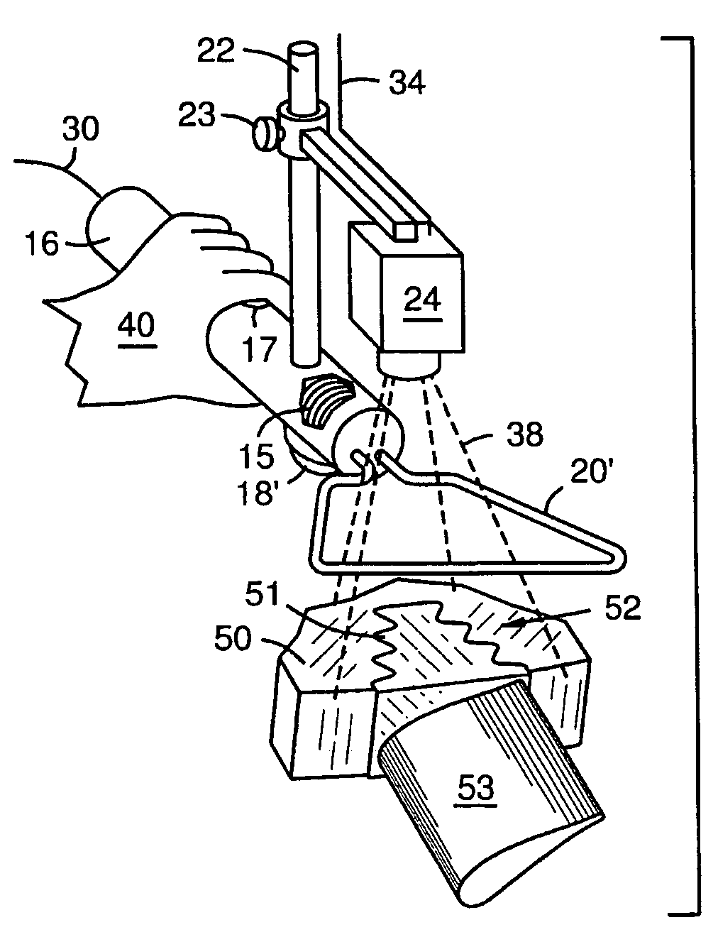
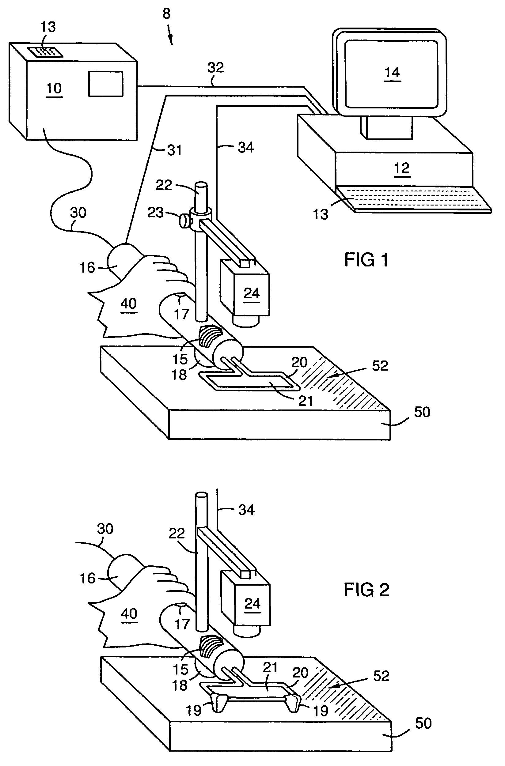
[0010]FIG. 1 illustrates a thermography system 8 with an electric current generator 10 electrically connected 32 to a processor or controller 12 with a display 14. The connection 32 provides control and status signals between the controller and the generator 10. The generator 10 provides pulsed alternating current (10 ms-1,000 ms bursts) to a transformer 15 in a handle 16 via an electrical cord 30. A digital infrared camera 24 may be mounted on the handle 16 on a support 22 and may be electrically connected 34 to the controller 12. The camera support 22 may have a camera position adjustment mechanism 23. An induction coil 20 extends from the transformer 15, and may have a generally planar frame shape. The induced current is highest directly underneath the coil winding and decreases with increasing lateral distance from the winding. Therefore, an inner and outer border area with a width defined by the distance from the winding where the current decays to a certain extent (for example...


PUM


Abstract

A hand-held thermography system (8). A generator (10) supplies current to a transformer (15) in a handle (16). An induction coil (20) connected to the transformer (15) extends from the handle (16). The induction coil (20) induces eddy currents in a test object (50), producing a thermal topography on a surface (52) of the object (50) that reveals structural features including defects in the object. An infrared camera (24) mounted on the transformer (16) digitizes images of the thermal topography. A controller (12) processes the images, displays them on a monitor (14), and stores them in a digital memory (11) for evaluation. Digitized positional data relating the position of the image to the surface may also be stored. An operator (40) presses a trigger (17), signaling the controller (12) to start current to the induction coil (20) and simultaneously to acquire and process one or more images from the camera (24). The images may be evaluated visually and / or by computerized analysis techniques for analyzing defects in the object.

Description

FIELD OF THE INVENTION[0001]The invention relates to the field of non-destructive evaluation of articles of manufacture by stimulating an article with electromagnetic energy, then imaging and evaluating a resulting topography of differential inductive heating on a surface of the article.BACKGROUND OF THE INVENTION[0002]Active thermography is a non-destructive evaluation (NDE) technique in which a non-destructive stimulation such as acoustic or electromagnetic energy is applied to a test object. The applied energy induces mechanical vibrations or electromagnetic currents (respectively) in the object, thereby producing an uneven temperature distribution in the object. Structural features and flaws in the object generate localized heat under such stimulation. A resulting temperature topography on a surface of the object is imaged with an infrared camera. Information about defects and the inner structure of the object can be obtained by evaluating the images individually or a time serie...

Claims


Application Information

Patent Timeline
Patent Type & Authority Patents(United States)
IPC IPC(8): G01J3/10
CPCG01N25/72
Inventor ZOMBO, PAUL J.SHANNON, ROBERT E.ROTHENFUSSER, MAXGOLDAMMER, MATTHIASHOMMA, CHRISTIANBAUMANN, JOACHIM
Owner SIEMENS ENERGY INC
Why Eureka
Try Eureka