Electric potential measuring instrument and image forming apparatus

a technology of image forming apparatus and measuring instrument, which is applied in the direction of instruments, electrographic processes, process and machine control, etc., can solve the problems of sensor accuracy disadvantage in measurement, and achieve the effect of facilitating the operation of observing the output signal that appears on the gate electrod

Inactive Publication Date: 2009-02-10
CANON KK
View PDF28 Cites 4 Cited by
  • Summary
  • Abstract
  • Description
  • Claims
  • Application Information

AI Technical Summary

Benefits of technology

[0011]In another aspect of the present invention, there is provided an image forming apparatus comprising an electric potential measuring instrument according to the invention and an image forming means, wherein the surface of the electric potential measuring instrument equipped with the gate electrode is arranged opposite to the surface to be measured for electric potential of the image forming means and the image forming means controls the image forming operation thereof by using the outcome of the signal detection of the electric potential measuring instrument. In this image forming apparatus, too, the characteristic of the electric potential measuring instrument is used efficiently.
[0012]Thus, according to the invention, the operation of observing the output signal that appears on the gate electrode is facilitated by changing the coupling capacitance between the electrode and the object of measurement.

Problems solved by technology

Such a sensor is disadvantageous in terms of accuracy of measurement because it is highly apt to be influenced by external noise.

Method used


Image

  • Electric potential measuring instrument and image forming apparatus
  • Electric potential measuring instrument and image forming apparatus
  • Electric potential measuring instrument and image forming apparatus

Examples


first embodiment

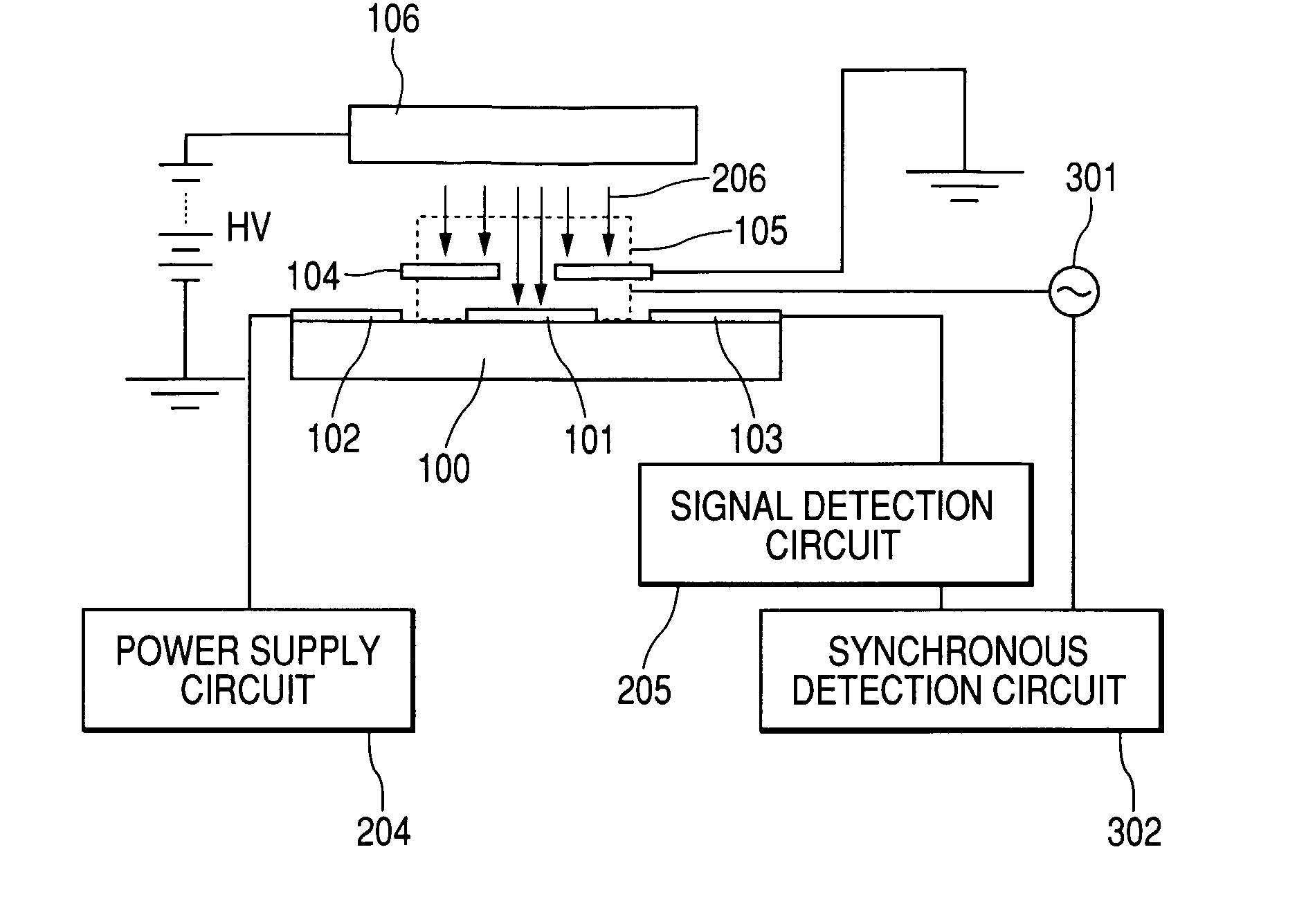
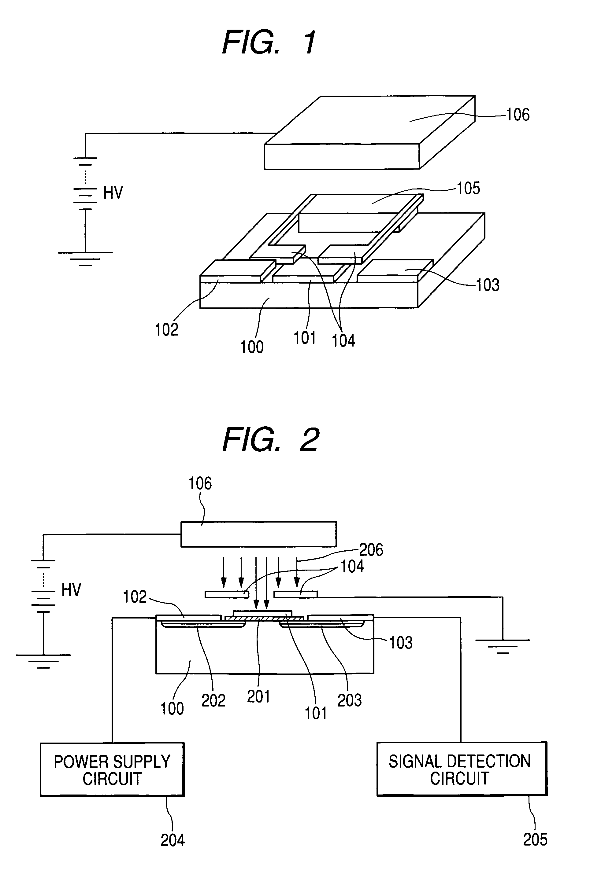
[0024]The first embodiment of the invention will be described by referring to FIGS. 1 through 3. FIG. 1 shows the overall configuration of this embodiment of electric potential sensor. Referring to FIG. 1, a signal detection electrode 101, which is a gate electrode, a source electrode 102 and a drain electrode 103 are formed on the surface of a plate-like semiconductor substrate 100 typically made of silicon (Si). An object of measurement 106 is arranged above and vis-à-vis the signal detection electrode 101 and a chopper 104 that is driven to oscillate periodically and a drive mechanism 105 for driving the chopper to oscillate are arranged on the substrate 100 and between the detection electrode 101 and the object of measurement 106.

[0025]FIG. 2 is a schematic cross sectional view of the electric potential sensor of the first embodiment, showing the structure of the substrate 100 and its surroundings in detail when the chopper 104 of the electric potential sensor is in a neutral st...

second embodiment

[0033]Now, the second embodiment of the present invention will be described by referring to FIGS. 5 and 6. This second embodiment is characterized in that a plurality of field effect type transistors and a plurality of choppers for modulating lines of electric force are formed on a same substrate and each of the field effect type transistors and each of the choppers have respective configurations same as those of their counterparts of the first embodiment.

[0034]A technique for improving the detection sensitivity of an electric potential sensor is to increase the surface area of the detection electrode. However, as the surface area of the detection electrode is increased, the chopper for modulating lines of electric force also needs to be made large. Then, there arises problems such as a high power consumption rate and a low drive frequency. The detection sensitivity of an electric potential sensor can be improved by arranging a large number of small detection electrodes so as to inc...

third embodiment

[0043]The number of lines of electric force that arrive at the detection electrode, which is a gate electrode of a transistor, is modulated in each of the above-described embodiments (so as to change the S in the above formula (2)). However, the coupling capacitance can be made to change by modulating the distance x between the object of measurement and the detection electrode as may be seen from the above formula (2). Such a technique is used in the third embodiment of the invention. FIG. 7 is a schematic illustration of the third embodiment of the present invention, which is an electric potential sensor, showing the configuration thereof.

[0044]FIG. 7 shows how the electric potential sensor is arranged relative to surface 1201, which is the object of measurement. In FIG. 7, numeral 1202 denotes a case for containing the electric potential sensor that covers a top portion of a swinging body 1104 except the parts of the detection electrodes. The case is made of an electrically conduc...


PUM


Abstract

The electric potential measuring instrument comprises an electrode arranged on a semiconductor substrate at a position opposite to the object of measurement and a modulator for modulating the coupling capacitance between the object of measurement and the electrode. The electrode is the gate electrode of a field effect type transistor. The modulated electric current that flows between the source diffusion region and the drain diffusion region of the field effect type transistor is synchronously detected by a detection circuit with the modulation frequency of the modulator. The output signal that appears on the gate electrode of a field effect transistor can be measured with ease by changing the coupling capacitance between the electrode of an electric potential measuring instrument and an object of measurement.

Description

TECHNICAL FIELD[0001]This invention relates to an electric potential measuring instrument (electric potential sensor) for measuring the electric potential of an object of measurement without contacting the latter and also to an image forming apparatus that can be used as a copying machine or a printer and comprises such an electric potential measuring instrument.BACKGROUND ART[0002]Known image forming apparatus comprising a photosensitive drum and adapted to form an image by electronic photography are required to keep the photosensitive drum electrified so as to uniformly show a certain electric potential. For this purpose, an electric potential measuring instrument is used to measure the electric potential of the electrified photosensitive drum and a feedback control system is operated to keep the photosensitive drum electrified so as to uniformly show a predetermined electric potential, utilizing the reading of the instrument.[0003]Now, the operation of a known electric potential ...

Claims


Application Information

Patent Timeline
Patent Type & Authority Patents(United States)
IPC IPC(8): G01R29/12G01R5/28G03G15/00
CPCG01R29/12G01R5/28
Inventor ICHIMURA, YOSHIKATSU
Owner CANON KK
Why Eureka
Try Eureka