
Implantable medical device with reconfigurable non-volatile program

a medical device and non-volatile programming technology, applied in the field of implantable medical devices, can solve the problems of inability to reprogramme, volatile program contents, loss,

Active Publication Date: 2009-02-10
LIVANOVA USA INC
View PDF94 Cites 48 Cited by
  • Summary
  • Abstract
  • Description
  • Claims
  • Application Information

AI Technical Summary

Benefits of technology

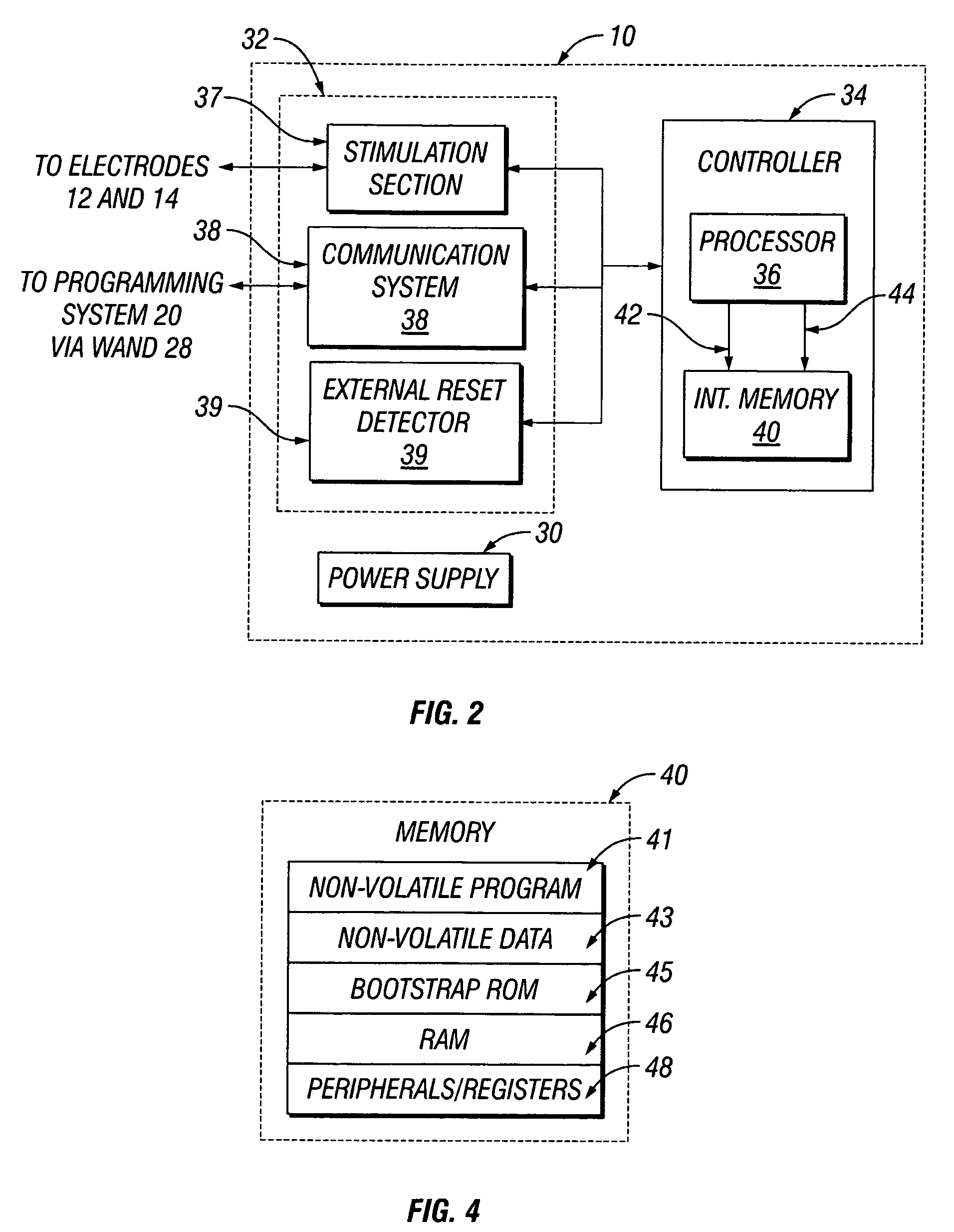
The patent describes a device with a non-volatile memory that can be updated with new instructions. The device includes an instruction processor and a telemetry system for non-invasive communication with an external device. The non-volatile memory stores instructions that control the operation of the device. The device can generate an erase control signal to erase at least a segment of the non-volatile memory and a write control signal to write one or more new instructions to the non-volatile memory, thereby modifying the operation of the device. The external device can send new instructions to the device telemetry system, which will execute the new instructions directly from the non-volatile memory. The method of updating the device involves storing a first program in the non-volatile memory, erasing at least a segment of the non-volatile memory, and writing a second program to the erased segment of the non-volatile memory. The preferred embodiments described herein do not limit the scope of the patent.

Problems solved by technology

However, when software improvements arise, there is a need for upgrades or modifications to the software stored in the IMD, and ROM and PROM memories have the inherent limitation that they cannot be reprogrammed without physically changing the memory in the IMD, thus necessitating an explant of the IMD.
Each of the methods currently used in the related art has limitations, as discussed below.
Various IMDs employ volatile RAM, wherein program contents are volatile and subject to loss due to power fluctuations.
One limitation of such a design is that loss of power results in an unrecoverable loss of the programming and the therapy parameters stored therein.
The requirement of error checking circuitry adds significant complexity to the IMD system.
Other IMDs of the related art use volatile, programmable RAM for the main program with a program back-up in ROM, wherein program contents in RAM may be lost due to power fluctuations, but upon losing power, the IMD reverts to the non-modifiable back-up program in stored in ROM.
One limitation of such a design is the requirement of both a RAM and a ROM of sufficient size to store the executable program.
While such a design minimizes the size of the RAM needed, such an approach also limits the degree of possible upgrade or modification based on the quantity of available RAM and the granularity of the tasks (i.e. the size of individual tasks relative to the code size and execution time).
Such a design does not solve the problem that both the RAM and the ROM must be of sufficient size to store the executable program and the processor cannot directly execute the program.
Additionally, a virtual memory design adds undesirable complexity to the IMD.
One limitation of such a design is that both the RAM and the FRAM must be of sufficient size to store the executable program.
Also, FRAM suffers from the deficiency that repeated read access of a FRAM location causes the FRAM to lose its non-volatility.
Specifically, the physical nature of the crystal employed by FRAM is such that an almost infinite number of writes is possible, but the crystal deteriorates with each read, causing the FRAM to lose its non-volatility after a number of reads (typically in the range of 10 billion reads).
The limited non-volatility lifetime of FRAM is particularly problematic for executable programs stored in the FRAM.
Such programs often contain execution loops that result in repeated access of the FRAM.
For applications such as the execution of software in an IMD, wherein relatively few writes are necessary, but, taking programming loops into account, vast numbers of reads are necessary, FRAM is thus inadequate.
Still further, when the program is executed directly from RAM, there is a need for error checking on all instructions prior to execution to prevent execution of an instruction altered by a power fluctuation, adding significant complexity to the IMD system.

Method used


Image

  • Implantable medical device with reconfigurable non-volatile program
  • Implantable medical device with reconfigurable non-volatile program
  • Implantable medical device with reconfigurable non-volatile program

Examples


Embodiment Construction

[0030]The present invention is susceptible to implementation in various embodiments. The disclosure of specific embodiments, including preferred embodiments, is not intended to limit the scope of the invention as claimed unless expressly specified. In addition, persons skilled in the art will understand that the invention has broad application. Accordingly, the discussion of particular embodiments is meant only to be exemplary, and does not imply that the scope of the disclosure, including the claims, is limited to specifically disclosed embodiments.

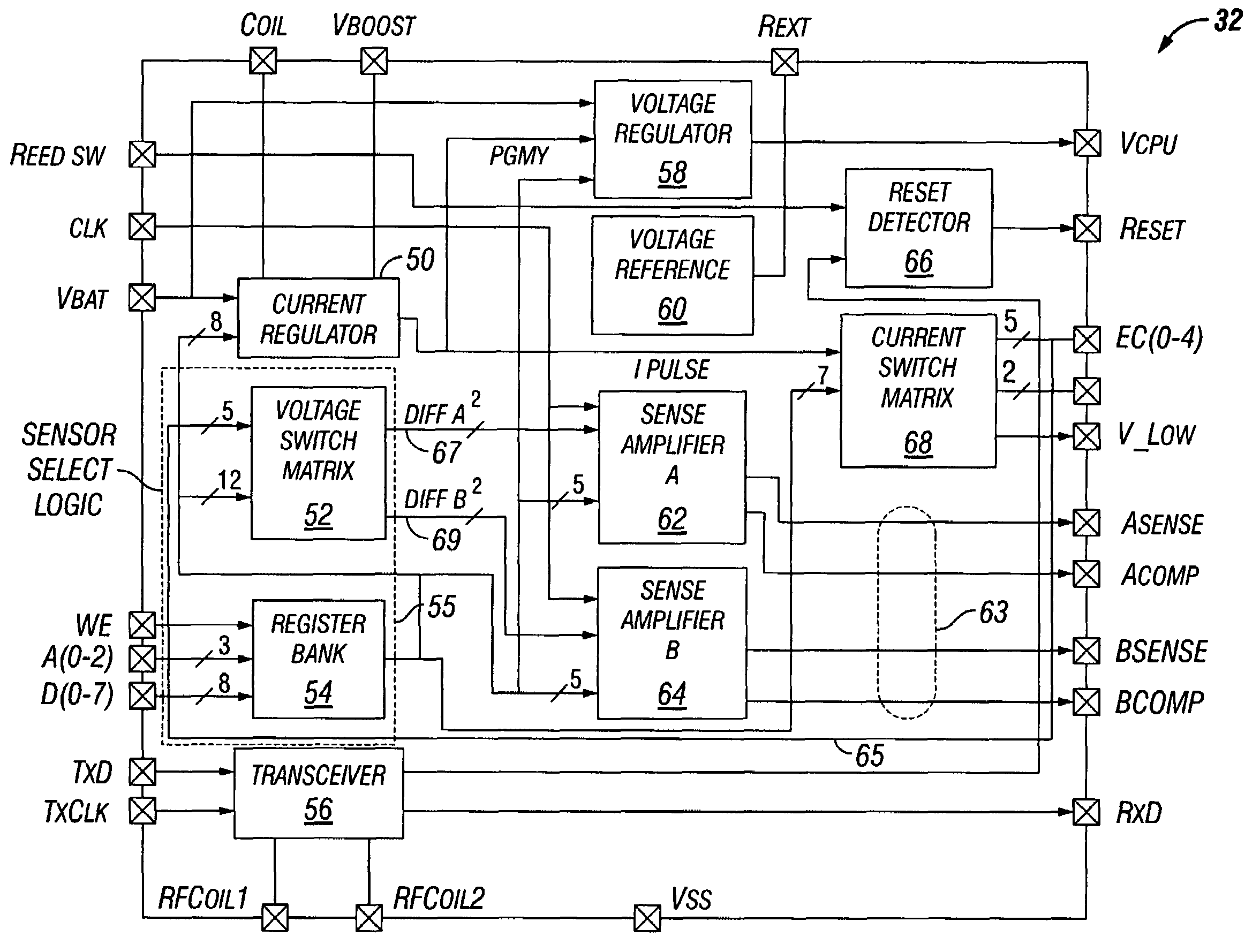
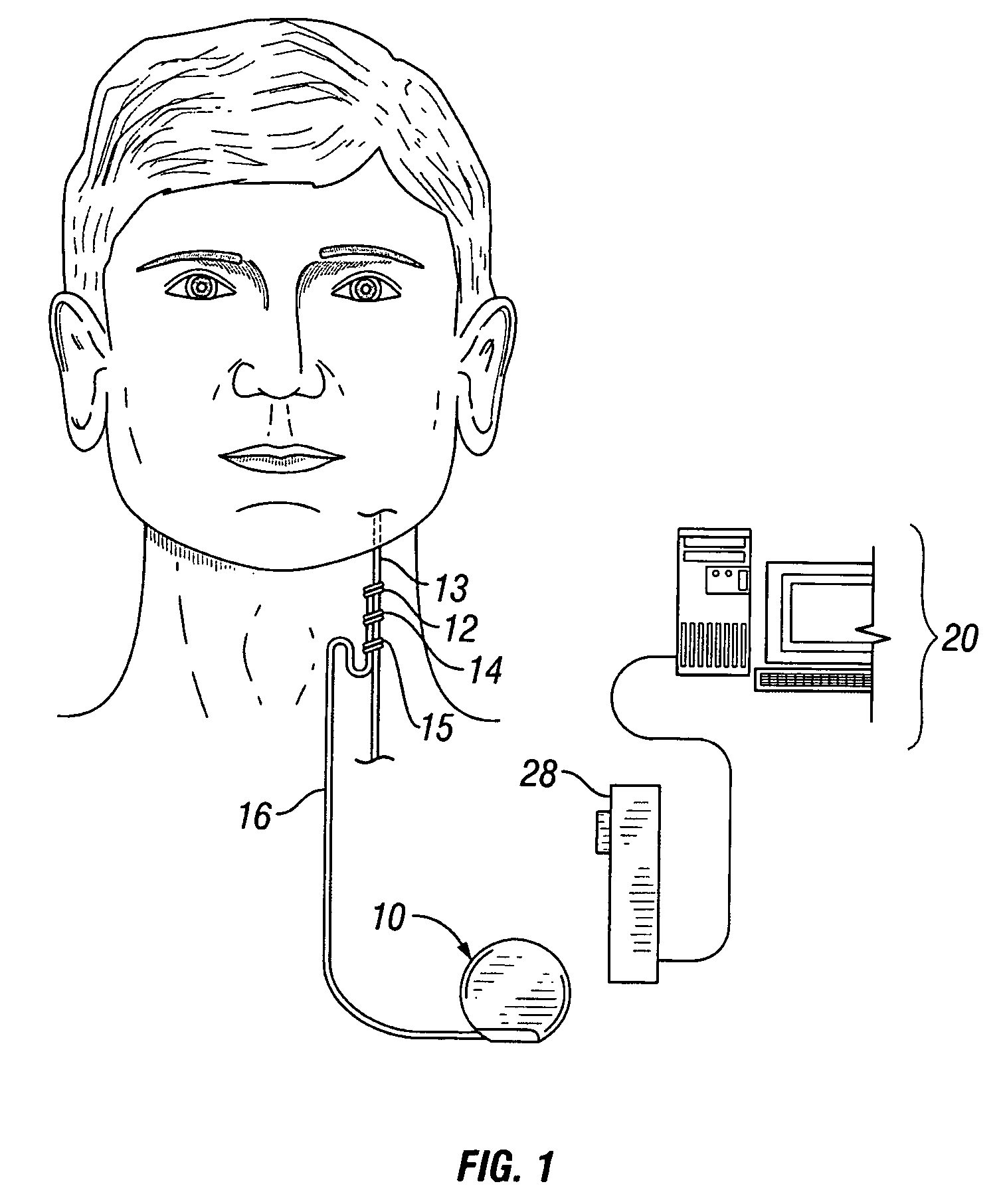
[0031]FIG. 1 illustrates an implantable medical device (“IMD”) 10 implanted in a patient. The IMD 10 may be representative of any of a variety of medical devices. At least one preferred embodiment of the IMD 10 comprises a neurostimulator for stimulating a neural structure in a patient, particularly a neurostimulator for stimulating a patient's cranial nerve such as a vagus nerve 13. Although the IMD 10 is described below in terms of a v...


PUM


Abstract

A device comprises a stimulus generator comprising an instruction processor. The stimulus generator is configured to deliver stimuli to a biological tissue. The device also comprises a non-volatile memory for storing instructions directly executable by the instruction processor, the instructions controlling, at least in part, the operation of the device. The instruction processor generates an erase control signal to erase at least a segment of the non-volatile memory and a write control signal to write one or more new instructions to at least a segment of the non-volatile memory, thereby modifying the operation of the device.

Description

BACKGROUND[0001]1. Technical Field[0002]The disclosed subject matter relates generally to implantable medical devices and more particularly to reconfigurable non-volatile programming in an implantable medical device.[0003]2. Background Information[0004]Various diseases and disorders of the nervous system are associated with abnormal neural discharge patterns. One treatment regimen for such diseases and disorders includes drug therapy. Another treatment technique includes the implantation in the patient of an implantable medical device that comprises a pulse generator for electrically stimulating a target location of the patient's neural tissue. In one such available treatment for epilepsy, the vagus nerve is electrically stimulated by a neurostimulator device substantially as described in one or more of U.S. Pat. Nos. 4,702,254, 4,867,164, and 5,025,807, all of which are incorporated herein by reference.[0005]Some implantable pulse generators used for electrical stimulation of neuro...

Claims


Application Information

Patent Timeline
Patent Type & Authority Patents(United States)
IPC IPC(8): G11C11/34
CPCA61N1/37264
Inventor ARMSTRONG, RANDOLPH K.ARMSTRONG, SCOTT A.
Owner LIVANOVA USA INC
Learn More