
Drum type washing machine

a drum type and washing machine technology, applied in other washing machines, washing machines with receptacles, textiles and papermaking, etc., can solve the problems of abnormal vibration and noise, eccentric load around the rotation shaft, and mass imbalance, so as to shorten the time required for dehydrating operation, shorten the time, and raise the drum speed

Active Publication Date: 2009-02-17
QINGDAO HAIER WASHING MASCH CO LTD +1
View PDF9 Cites 49 Cited by
  • Summary
  • Abstract
  • Description
  • Claims
  • Application Information

AI Technical Summary

Benefits of technology

The present invention provides a drum type washing machine with a speed change detector and a dehydration start-up controller for carrying out the dehydration process efficiently and preventing abnormal vibration or noise. The speed change detector detects the change in speed of the drum when the motor is controlled to rotate at a constant speed. The dehydration start-up controller detects the timing where the speed change becomes smaller than a predetermined value and then accelerates the drum to a speed where the laundry articles are pressed onto the inner circumferential wall of the drum by centrifugal force. The dehydration start-up controller may also reverse the rotating direction of the drum to increase the likelihood of loosening and distributing the laundry articles even if there is a small chance of a mass of tightly tangled laundry articles.

Problems solved by technology

In this type of washing machine, an uneven distribution of the laundry on the inner circumferential wall will cause a mass imbalance (i.e. an eccentric load) around the rotation shaft.
The outer tub in turn collides with the inside of the housing and causes it to vibrate.
As a result, an abnormal vibration and noise occurs.
For this purpose, it is necessary to loosen the laundry articles because they are usually tangled with each other after the washing or rinsing process.
However, the above-described conventional control method does not always ensure that the drum speed is raised at a good timing when the laundry articles are adequately loosened and easy to distribute.
Therefore, the possibility of appropriately distributing the laundry articles into a state where the eccentric load is adequately small is weak.
Repeating such a process often requires a very long time until the dehydration process is actually started.
Usually, however, once the outer tub starts a strong vibration due to an uneven distribution of the laundry during the low speed rotation of the drum, the vibration will not immediately fade away even after the laundry is adequately distributed.
This means that it is impractical to continuously check and determine the massing or gathering state of the laundry during the low speed rotation of the drum.
Therefore, it is essential to continuously check the state of the laundry contained in the drum, otherwise the drum speed cannot be raised at the best timing where the laundry is adequately distributed.
For this reason, the aforementioned conventional washing machine often fails to detect the best timing for increasing the drum speed and resultantly takes a long time for the loosening operation.
In the case the laundry is tightly tangled in a mass form, there is only a small chance that the laundry articles will be loosened by continuing the loosening operation for a long period of time.
However, the aforementioned conventional washing machine cannot distinguish the case where the laundry is in the form of an extremely tight mass from the case where the laundry is a simple pile of laundry articles that are not tightly tangled.
As a result, the loosening operation often continues even in the former case where the loosening effect is least expected, consuming an unnecessarily long period of time until the start of the dehydration process.

Method used


Image

  • Drum type washing machine
  • Drum type washing machine
  • Drum type washing machine

Examples


Embodiment Construction

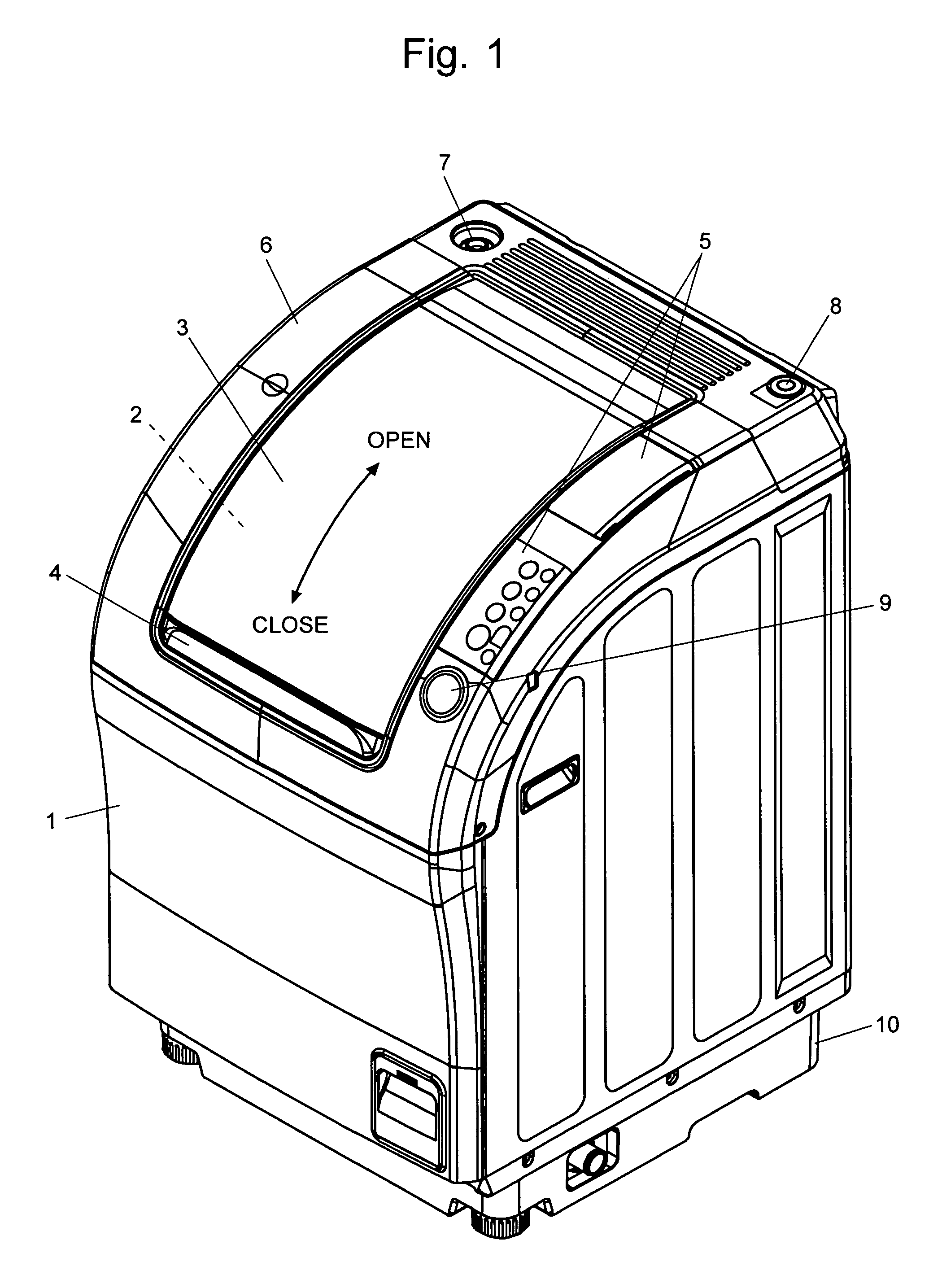
[0034]A drum type washing machine as an embodiment of the present invention is described with reference to the attached drawings.

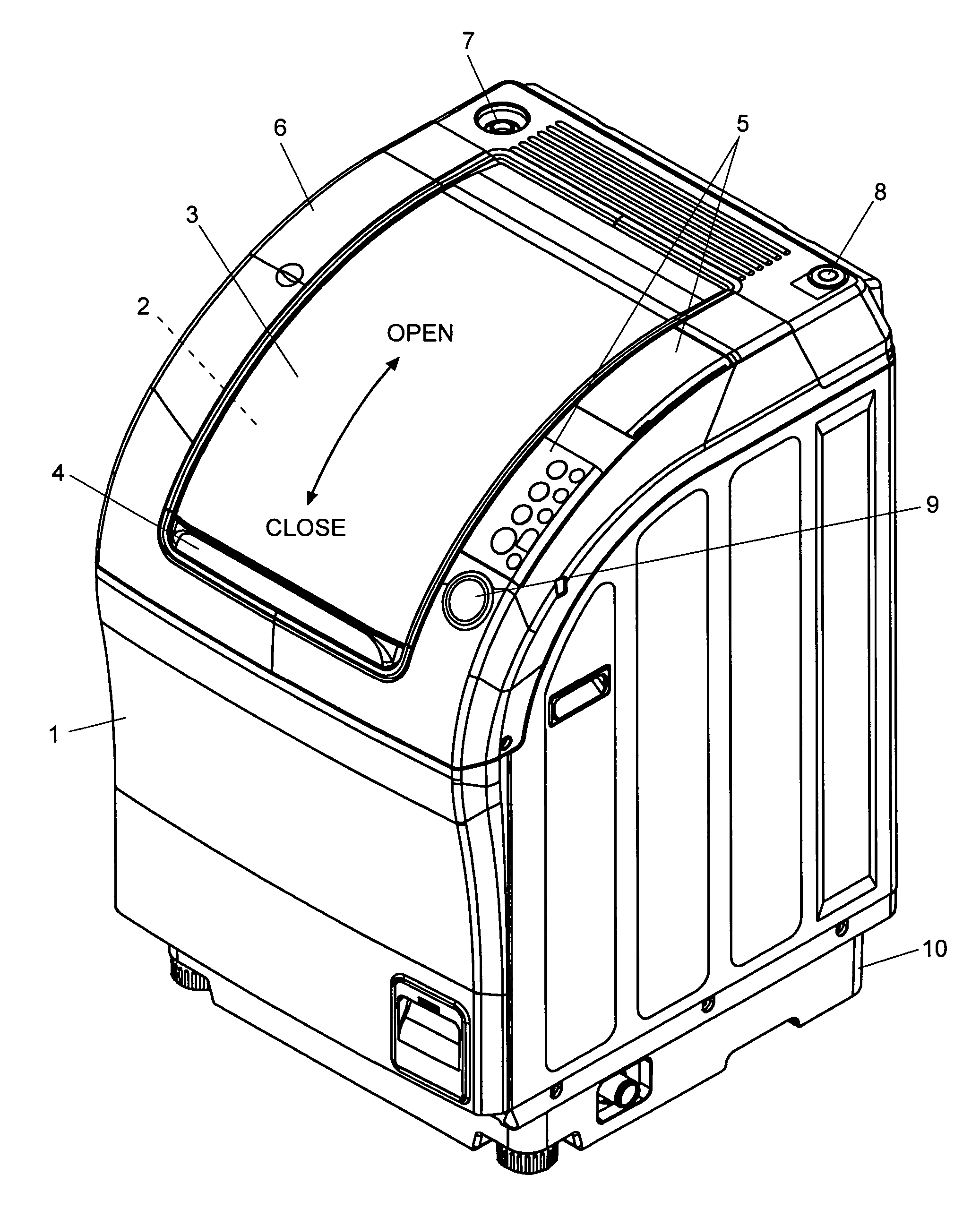
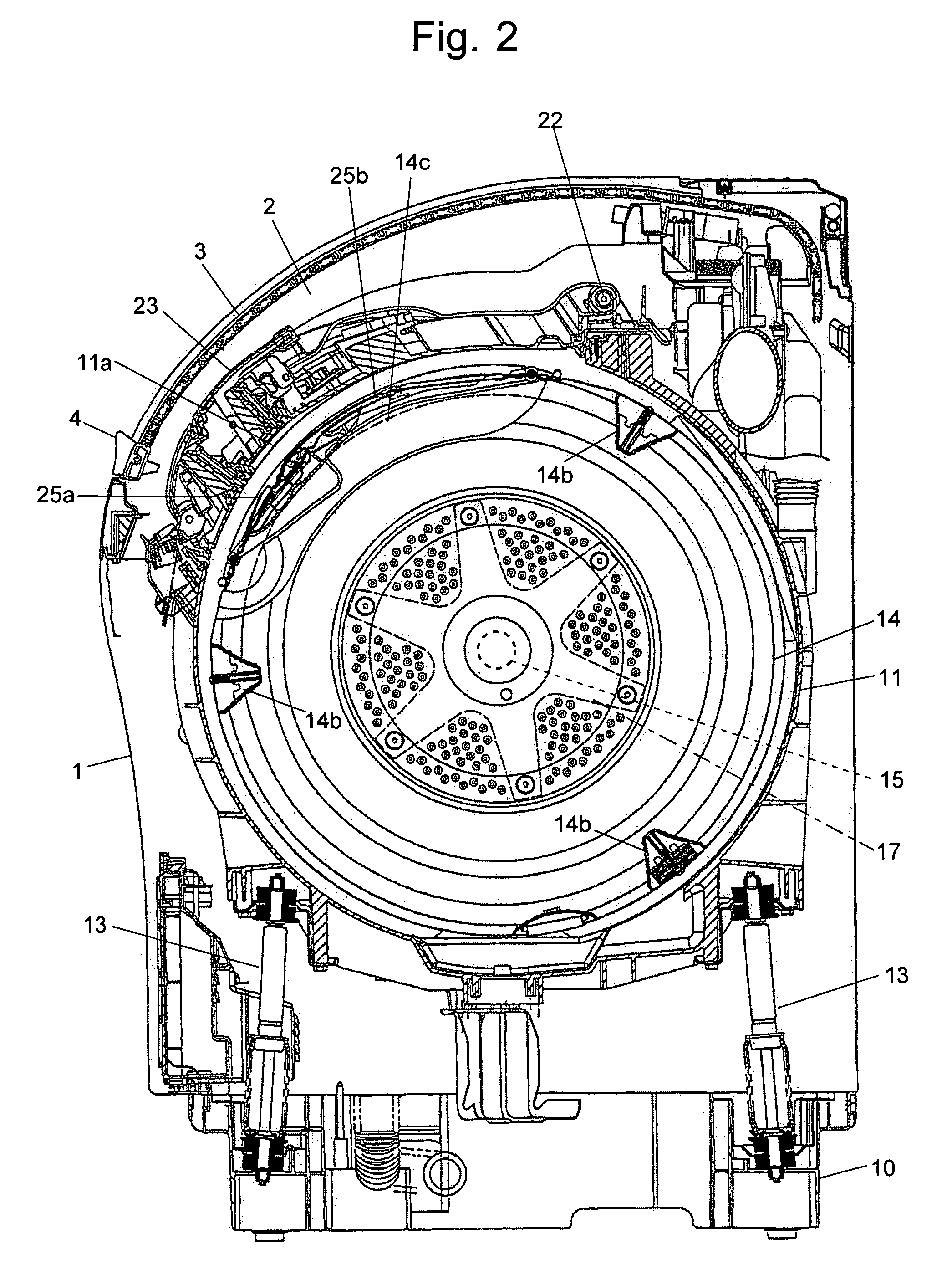
[0035]FIG. 1 is a perspective view of the drum type washing machine, FIG. 2 is a vertical sectional view of the main part of the drum type washing machine viewed from the right side, and FIG. 3 is a vertical sectional view of the main part of the drum type washing machine viewed from the front.

[0036]The housing 1 of the present washing machine has a curved surface extending from the top to the front and having a large opening 2 through which the laundry is to be loaded. The opening 2 can be closed with the shutter 3 consisting of slats linked in series, which can slide along the curved surface in the rear-to-front direction. With the shutter 3 in the closed position, if the user presses the button 9 located on the right side of the shutter 3, the shutter 3 automatically slides backwards to uncover the opening 2, as indicated by the arrow in FIG. 1. To clos...


PUM


Abstract

The present invention provides a drum type washing machine capable of adequately distributing the laundry articles along the inner circumferential wall of the drum at the start-up of the dehydrating operation with high probability, thereby reducing the start-up time of the dehydration. In an embodiment of the present invention, the drum is controlled to rotate at a constant speed 50 r.p.m. to agitate the laundry articles (Step S12), and the drum speed is almost continuously monitored. If the change in the speed does not exceed 1.5 r.p.m. for 0.5 second (Steps S13 through S16), the laundry articles are loosened and easy to distribute. Therefore, the drum speed is raised to 80 r.p.m. (Steps S17 and S18). If the eccentric load detected at this speed does not exceed a predetermined value (Steps S19 and S20), the laundry articles are adequately distributed along and pressed onto the inner circumferential wall of the drum. If a sudden change in the speed has been detected within a short period of time that is less than 36 milliseconds (Step S22), the laundry articles are tangled in a mass form. Therefore, the rotating direction of the drum is reversed, and the agitating direction is restarted in the opposite direction (Step S21).

Description

[0001]The present invention relates to a drum type washing machine and more specifically to a technique for suppressing or reducing vibration incurred during the rotary dehydration process.BACKGROUND OF THE INVENTION[0002]In a drum type washing machine, an approximately cylindrical drum having a circumferential wall with a large number of perforations is mounted on a horizontal or inclined rotation shaft. In the dehydrating operation, the drum is rotated at high speeds so that the laundry contained in the drum is squeezed and the water held therein is removed. In this type of washing machine, an uneven distribution of the laundry on the inner circumferential wall will cause a mass imbalance (i.e. an eccentric load) around the rotation shaft. In this state, the drum strongly vibrates if it is rotated at a high speed. The vibration of the drum leads to a vibration of the outer tub enclosing the drum. The outer tub in turn collides with the inside of the housing and causes it to vibrat...

Claims


Application Information

Patent Timeline
Patent Type & Authority Patents(United States)
IPC IPC(8): D06F33/02D06F37/38B08B3/12D06F35/00D06F37/20
CPCD06F35/007D06F37/203D06F33/48D06F33/40D06F34/16D06F2105/56D06F2103/24D06F2103/04D06F2103/26D06F2105/52
Inventor HIRASAWA, YUJIKAWAGUCHI, TOMONARI
Owner QINGDAO HAIER WASHING MASCH CO LTD
Learn More