Coupling structure of heat transfer plate and gasket of plate type heat exchanger

a technology of heat transfer plate and gasket, which is applied in indirect heat exchangers, lighting and heating apparatuses, laminated elements, etc., can solve the problems of frequent leakage of fluids, restricting the kind, use temperature and pressure of fluids usable with plate type heat exchangers, and affecting the performance of heat transfer plates and gaskets. the effect of simplifying the coupling structur

Active Publication Date: 2009-02-17
DHP ENGINNEERING
View PDF10 Cites 17 Cited by
  • Summary
  • Abstract
  • Description
  • Claims
  • Application Information

AI Technical Summary

Benefits of technology

[0010]Therefore, the present invention has been made in view of the above problems, and it is an object of the present invention to provide a coupling structure of a heat transfer plate and a gasket for use in a plate type heat exchanger wherein a gasket groove, formed along the outer circumference of respective fluid passage holes and the heat transfer plate, and the gasket to be inserted into the gasket groove have a toothed engagement coupling structure, whereby the coupling structure of the heat transfer plate and the gasket is remarkably simplified, while the contact area between the heat transfer plate and the gasket and the resulting coupling strength can be greatly improved, and thus, pressure resistance of the plate type heat exchanger can be greatly improved to allow the plate type heat exchanger to be easily applied to high temperature and pressure heat exchanger facilities.

Problems solved by technology

However, in spite of the above described many advantages, the plate type heat exchanger is problematic because the seal between the respective heat transfer plates 10 is obtained only using the gaskets 20 made of rubber.
This heavily restricts the kind, use temperature, and pressure of fluids usable with the plate type heat exchanger.
More specifically, if the hardness of the gasket 20 is deteriorated due to usage at high temperature and pressure that is exhibited in a lubricant cooler of ships, an internal pressure P applied in an outward direction of the heat transfer plate 10 causes the gasket 20 to rotate in the gasket groove 13 or to be pushed out of the heat transfer plate 10, resulting in a frequent leakage of fluids.
This tends to induce a severe deterioration in the continuous operation property of the heat exchanger, and results in environmental contamination and dangerous large-scale accidents when the heat exchanger is used in a petrochemical plant.
The former adhesive coupling manner, however, has several problems, such as corrosion of the heat transfer plate 10 and the gasket 20 by the adhesive, and unintentional chemical actions between the adhesive and heat exchanging fluids.
Also, in the case of the latter non-adhesive coupling manner, the coupling structure disadvantageously increases the manufacturing costs of the heat transfer plate 10 or the gasket 20 and complicates the process of fixing the gasket 20 to the heat transfer plate 10, resulting in a deterioration in the overall productivity and price competitiveness of the plate type heat exchanger.

Method used


Image

  • Coupling structure of heat transfer plate and gasket of plate type heat exchanger
  • Coupling structure of heat transfer plate and gasket of plate type heat exchanger
  • Coupling structure of heat transfer plate and gasket of plate type heat exchanger

Examples


Embodiment Construction

[0016]Now, preferred embodiments of the present invention will be explained with reference to the accompanying drawings.

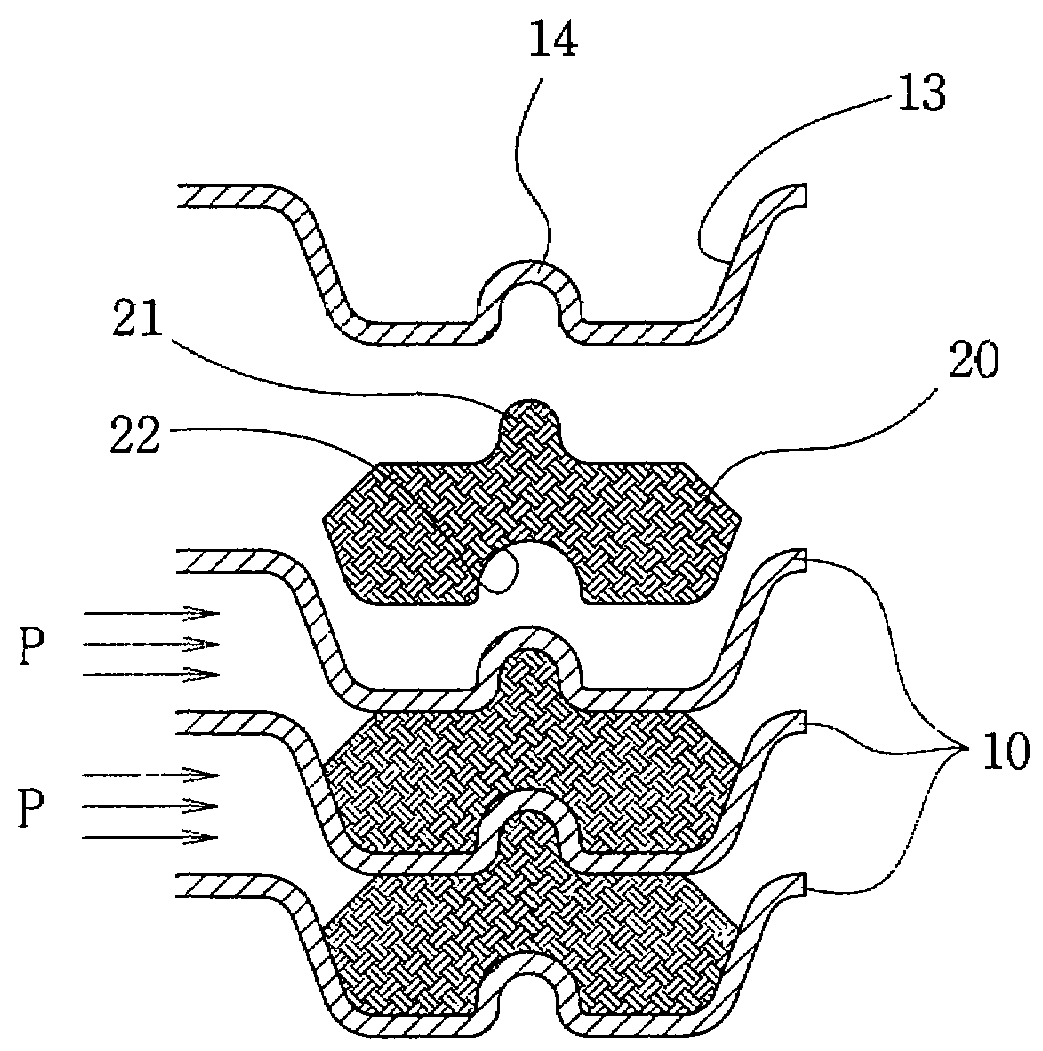
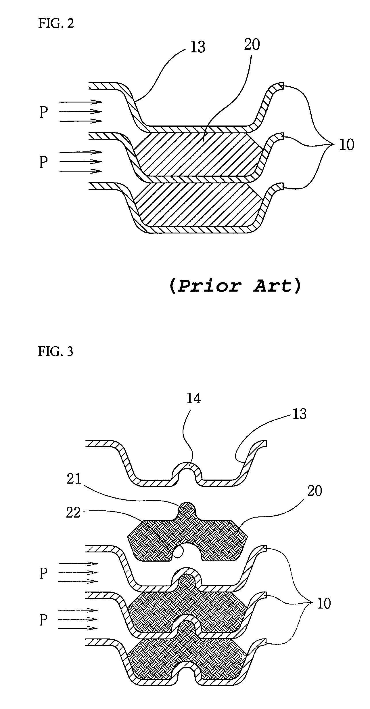
[0017]FIGS. 3 and 4 are enlarged partial side sectional views illustrating the coupling structure of a heat transfer plate and a gasket according to the preferred embodiments of the present invention. Hereinafter, parts corresponding to those of the prior art are denoted by the same reference numerals as those of the prior art.

[0018]Referring first to FIG. 3, the coupling structure of a heat transfer plate and a gasket, for use in a plate type heat exchanger, according to the embodiment of the present invention comprises: a protrusion 21 formed at an upper surface of a gasket 20 having an approximately hexahedral cross section; a recess 22 formed at a lower surface of the gasket 20 and having the same shape as the protrusion 21; and an inverted U-shaped prominent portion 14 formed at the bottom of a gasket groove 13 of a heat transfer plate 10 and having the same s...


PUM


Abstract

A coupling structure of a heat transfer plate and a gasket for use in a plate type heat exchanger. The heat transfer plate has a groove for receiving the gasket. The coupling structure includes a protrusion formed at a first surface of the gasket, a recess formed at a second surface of the gasket having the same shape as the protrusion, and an inverted U-shaped prominent portion formed at the bottom of the gasket groove of the heat transfer plate. A prominent portion of the heat transfer plate is tightly inserted into the recess of the gasket, and the protrusion of the gasket located under the prominent portion of the heat transfer plate is inserted into a recessed internal space of the prominent portion.

Description

BACKGROUND OF THE INVENTION[0001]1. Field of the Invention[0002]The present invention relates to a structure of coupling a heat transfer plate and a gasket, for use in a plate type heat exchanger, to each other.[0003]2. Description of the Related Art[0004]Referring to FIG. 1, a conventional heat transfer plate, for use in various kinds of plate type heat exchangers, is shown in plan view. As shown in FIG. 1, the heat transfer plate 10, made of a thin metal plate, includes: corrugated heat transfer channels 11 formed at the substantially overall surface thereof; and first and second fluid passage holes 12 and 12′ perforated through respective corners thereof at the outer side of the heat transfer channels 11. In use, a plurality of the heat transfer plates 10 are closely stacked one above another so that first and second heat exchanging fluids, i.e. a first heating or cooling fluid and a second fluid to be heated or cooled, are able to alternately flow between the stacked heat transf...

Claims


Application Information

Patent Timeline
Patent Type & Authority Patents(United States)
IPC IPC(8): F28F3/08F28F3/02F28D9/00
CPCF28F3/10F28F3/02F28D9/00
Inventor SONG, YOUNG-HO
Owner DHP ENGINNEERING
Why Eureka
Try Eureka