
Flexible manufacturing system having modular work stations

a manufacturing system and modular technology, applied in the field of flexible manufacturing system, can solve the problems of not being able to easily adapt to other tasks, not being able to achieve the final piece shape and tolerances, and the need for pallet pools to be kept in stock, etc., and achieving the effect of reducing the number of pallet pools, and increasing the cost of production

Inactive Publication Date: 2009-02-17
WES TECH AUTOMATION SOLUTIONS
View PDF22 Cites 72 Cited by
  • Summary
  • Abstract
  • Description
  • Claims
  • Application Information

AI Technical Summary

Benefits of technology

[0021]It is a significant feature and distinct advantage of the present invention to provide a flexible manufacturing line and manufacturing process providing flexibility and adaptability to variation, improved maintenance of reference position on the fixture during manufacture, improved accessibility to machining stations during operation, and increased safety. Accordingly, the flexible manufacturing line and manufacturing process described, illustrated and claimed herein includes an automated flexible manufacturing system capable of modular interchangeability of the machining stations, comprising a track for transporting a combination comprising a workpiece mounted on a pallet, the track transporting the combination pallet and workpiece along a single central track pathway defined by essentially upwardly extending walls located on either side of the single central pathway, which may be a rectilinear track, plural modular machining stations capable of being disposed substantially adjacent the track, each machining station being modularly attachable and detachable from the track, either with or without the associated track segment, and, when attached to the track, providing an automated machining station for processing the workpiece mounted on the pallet at a location removed from the track; and a workpiece diverter disposed at least at one of the plural automated machining stations, the workpiece diverter including a diverter mechanism capable of transferring the pallet and workpiece combination from the track and to the automated machining station, the track having substantially transverse channels extending through one of the essentially upwardly extending walls to permit the pallet and workpiece combination to be diverted from the single central track pathway and to the associated automated machining station, the workpiece diverter further having a retracting mechanism capable of retracting the pallet and workpiece combination from the machining station and onto the single central pathway of the track.
[0022]Ideally, the flexible manufacturing system is capable of modular interchangeability of the work stations, so that different sequencing and interoperability of the machining centers is available to provide flexibility in setting up the sequence and order of the several operations available for processing of the workpiece at each station. The interchangeability feature is provided by detaching the desired track segment, together with its attached machine station, moving it to the desired location on the conveyor, and reattaching the track segment in the track at the desired location. Preferably, the flexible manufacturing system according to the present invention is capable of multi-axis machining without requiring any change in the set-up of the work stations.
[0023]In another embodiment, the invention comprises a trunnion for use in a flexible manufacturing system including a trunnion body having freedom to rotate around at least one or, preferably, two axes of freedom, an attachment mechanism for precisely attaching a pallet to the trunnion body, the pallet having an underside, and a plurality of pallet grooves disposed on the underside of the pallet, the pallet grooves having a preselected size, configuration and orientation, the attachment mechanism including a plurality of elongated, parallel clamping bars configured to have a cross-section smaller than, but essentially corresponding to the configuration and orientation of the pallet grooves, wherein the clamping bars are capable of insertion into the pallet grooves in a close fitting engagement, and an actuator providing for engagement of the pallet grooves relative to the clamping bars.
[0024]These and additional features will be described below in greater detail in the detailed description of the preferred embodiments. Benefits derived from the feature of the present invention include the capability of five side machining without requiring set-up change or manual intervention, and also in precision automatic positioning and orientation of the workpieces prior to machining operations being performed thereon.

Problems solved by technology

In the manufacturing of certain metal workpieces to provide finished metal products, it is not possible to achieve the final piece shape and tolerances by metal casting, forging, and extrusion or forming alone.
Dedicated stations are constructed to perform a fixed set of operations and cannot be easily adapted to perform other tasks.
These types of fixtures, and the pallet pools required to be kept in stock, also tend to be relatively expensive.
This usually requires cumbersome and time-consuming manual workpiece set-up operations, which utilize labor-intensive processes.
Thus, full automation of the flexible manufacturing system is not achieved, and the multiple clamps that are required between the workpiece and the machining station often lead to loss of precision and of repeatability in positioning, leading to a loss of precision and in repeatability thereby greatly reducing the productivity or yield rate and making the manufacturing process less economical.
Nevertheless, previous automated systems have suffered from various drawbacks.
For example, transfer of workpieces between work stations has remained labor intensive, slow, and / or inflexible (i.e., not easily adaptable to process changes or substitutions).
Overall precision, accuracy and repeatability of positioning suffers due to a loss of an exact registration in a reference position between fixtures or the requirement for multi-axis positioning and orientation.
Another disadvantage has been the inaccessibility of the CNC machines during operation, making observation and maintenance more difficult.
None of the prior art systems or methods known heretofore teach a flexible system capable of interoperability without requiring the removal and transfer of a workpiece or workpiece / pallet combination from one pallet capable of processing the workpiece in one orientation to another pallet capable of processing the workpiece in another orientation, or conversely, requiring vertical withdrawal of the pallet and workpiece structure, for example, by a gantry system.
However, such systems, commonly called “transfer lines,” are suited only for large batch jobs where the same parts or family of parts are made in great numbers.
It is not well suited to providing smaller numbers (on the order of 1-3 parts, for example) of finished workpieces or different parts, for example ones or twos of a particular part that are made on a monthly basis.
Also, it cannot provide easy interchangeability of the operations provided by the plural workpiece machining centers.

Method used


Image

  • Flexible manufacturing system having modular work stations
  • Flexible manufacturing system having modular work stations
  • Flexible manufacturing system having modular work stations

Examples


Embodiment Construction

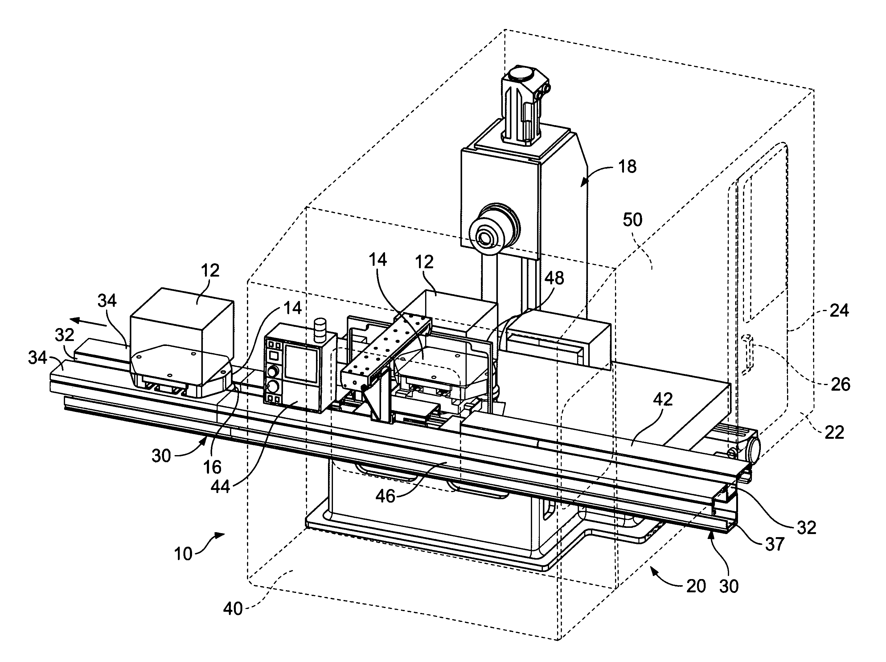
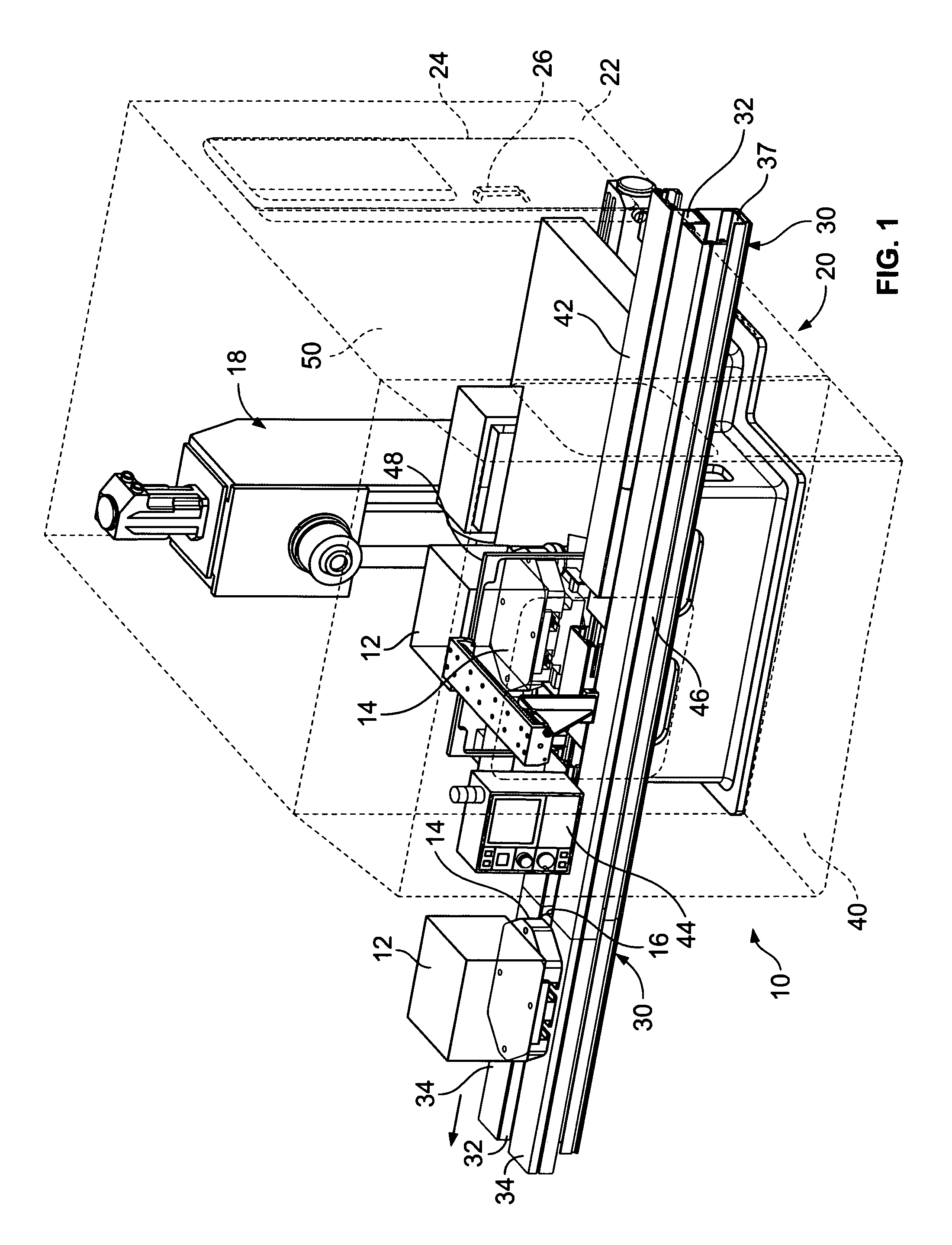
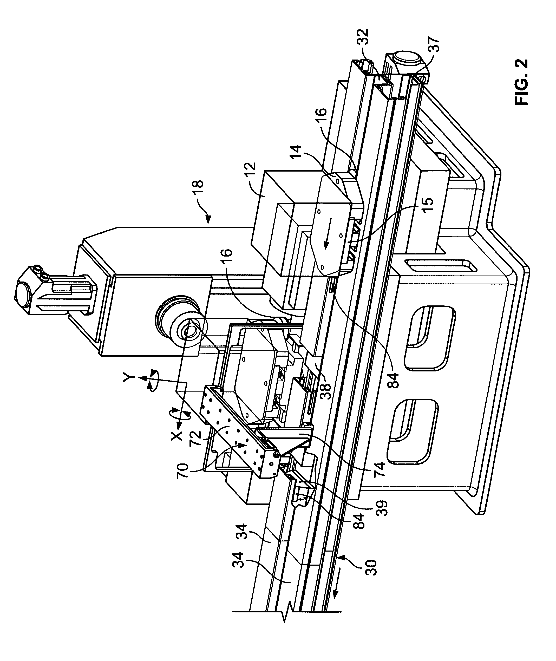
[0035]Referring now to FIGS. 1-6 together and separately, where appropriate, one embodiment of the inventive flexible machining system 10 is shown at different stages of the machining operations on the workpiece by the machining system. Specifically referring to FIG. 1, workpieces 12 are shown schematically as a cubic box, representing the nominal size of the total cutting envelope. Of course and actual workpiece 12 would appear in an actualized shape.

[0036]A first workpiece 12 is shown in the process of being transferred away from the machining module 20 following completion of its machining operations at that station. The workpiece 12 is being transported by the pallet 14, to which it is affixed, and along the track 32 of the conveyor 30. Once the machining operations performed on the workpiece have been completed, the conveyor 30 transports the workpiece 12 in the direction of the arrow to the next machining or other station (not shown in FIG. 1) in the system 10. The conveyor 30...


PUM

PropertyMeasurementUnit
Sizeaaaaaaaaaa
Flexibilityaaaaaaaaaa

Abstract

A flexible manufacturing system utilizing modular work stations configured to provide asynchronous operations on a plurality of work pieces mounted on fixtures or pallets that are transported through the system by means of a conveyor or rail arrangement. The pallets are diverted from the track on which they are transported linearly to a desired machining module adjacent to, but removed from, the track, such that the machining is performed in a chamber isolated from the track. Each machining module may be utilized in more than one location on the track and the modules may be interchanged depending on the desired operation sequence and the tools available in each of the machining station modules.

Description

REFERENCE TO RELATED APPLICATIONS[0001]This is a non-provisional of U.S. Provisional Application Ser. No. 60 / 838,705, filed on Aug. 19, 2006, and which is incorporated by reference herein.BACKGROUND OF THE INVENTION[0002]1. Field of the Invention[0003]This invention relates generally to a flexible manufacturing system and more specifically to such a system utilizing modular work stations configured to provide asynchronous operations on a plurality of work pieces mounted on fixtures or pallets that are transported through the system by means of a conveyor arrangement.[0004]2. Background Art[0005]In the manufacturing of certain metal workpieces to provide finished metal products, it is not possible to achieve the final piece shape and tolerances by metal casting, forging, and extrusion or forming alone. Part manufacture usually includes several different machining operations that must be applied to the original casting / forging, such as shaping, drilling, boring, milling, cutting, and ...

Claims


Application Information

Patent Timeline
IPC IPC(8): B65G37/02B65G47/24
CPCB23Q7/1426B23Q37/007Y10T29/5124Y10T29/5196Y10T409/305656
Inventor WESKAMP, ROBERTNORDSTROM, ERIC WALTERARENDS, JASON
Owner WES TECH AUTOMATION SOLUTIONS
Learn More