Method for catalytic growth of nanotubes or nanofibers comprising a NiSi alloy diffusion barrier

a diffusion barrier and nanotube technology, applied in the direction of crystal growth process, polycrystalline material growth, condensed vapor growth, etc., can solve the problems of poor insulating material, poor growth control of nanotube/nanofiber, and inability to grow nanotube/nanofiber effectively

Inactive Publication Date: 2009-02-17
THALES SA
View PDF21 Cites 59 Cited by
  • Summary
  • Abstract
  • Description
  • Claims
  • Application Information

AI Technical Summary

Benefits of technology

[0022]The invention thus consists in depositing a thin layer of second material constituting the catalyst on the upper layer of first material and then in annealing at a temperature greater than or equal to the nanofiber / nanotube growth temperature. Thus, an alloy stable at the annealing temperature Ta, and therefore at the nanotube / nanofiber growth temperature Tg, is formed (where Tg<Ta). Consequently, when catalyst spots are subsequently used, these do not react with the alloy formed beforehand and they allow effective catalytic nanotube / nanofiber growth.

Problems solved by technology

However, if during the step of raising the temperature of the substrate or support the catalyst aggregates diffuse into or are dissolved in the substrate or support, there will therefore be no nanotube / nanofiber growth.
If the barrier is not very effective, the growth of nanotubes / nanofibers will be poorly controlled.
SiO2 is an excellent barrier but it is an insulating material and therefore poorly suited in the case in which it is necessary to electrically connect the nanotubes.
SiO2 rapidly degrades as the electrical current flows and it then loses its insulating properties.

Method used


Image

  • Method for catalytic growth of nanotubes or nanofibers comprising a NiSi alloy diffusion barrier
  • Method for catalytic growth of nanotubes or nanofibers comprising a NiSi alloy diffusion barrier
  • Method for catalytic growth of nanotubes or nanofibers comprising a NiSi alloy diffusion barrier

Examples


1st example

Material M: Silicon

Material A: Nickel

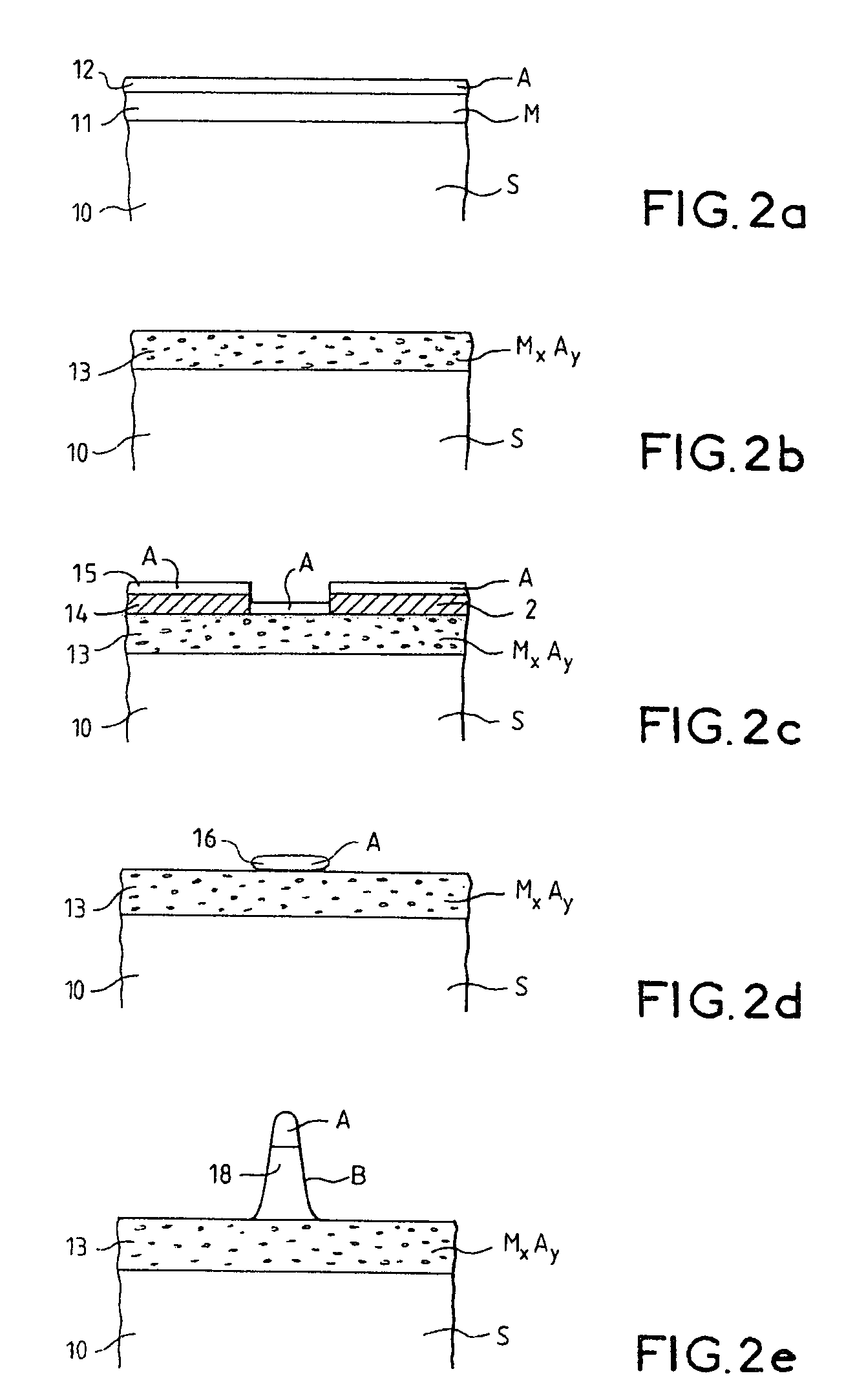
[0045]In the case of a silicon substrate or of a thin silicon layer deposited on a substrate, a thin nickel layer is deposited on the silicon. An annealing operation at 750° C. is then carried out so as to provide the compound NiSi.

[0046]The addition of platinum prevents the formation of the alloy NiSi2 and therefore allows only the compound NiSi to be obtained (J. F. Liu et al., J. Appl. Phys. Vol. 90 p. 745 (2001)). The NiSi alloy then constitutes an effective diffusion barrier against nickel if the nanotube growth temperature is below 750° C. It should be noted that the localized and oriented growth of carbon nanotubes may be obtained at 700° C. (K. B. K. Teo et al., Appl. Phys. Lett. Vol. 79 p. 1534 (2001)).

[0047]It is also possible to carry out the annealing at 850° C. so as to form NiSi2, which constitutes a diffusion barrier for nanotubes / nanofibers whose growth temperature is below 850° C.

[0048]A higher nanotube growth temperature (˜800° ...

2nd example

Material M: Silicon

Material A: Cobalt

[0050]In this second example, a cobalt layer is deposited on the surface of a silicon layer. To obtain a uniform CoSi2 alloy and therefore to prevent the formation of the CoSi phase, the annealing may advantageously be carried out at a temperature above 600° C.

[0051]A thickness of around 30 to 60 nm of cobalt makes it possible to obtain, after annealing at 800° C. the CoSi2 alloy (Y. J. Yoon, J. Vac. Sci. Technol. B17 p.627 (1999)). This compound formed at 800° C. then becomes an effective diffusion barrier for the cobalt catalyst, if the nanotube growth temperature is below 800° C.

3rd example

Material M: Silicon

Material A: Iron

[0052]An FeSi2 barrier layer may advantageously be formed by annealing an iron layer on the silicon surface at 700° C. This barrier layer may be used for the growth of nanotubes / nanofibers at temperatures below 700° C.


PUM

PropertyMeasurementUnit
thicknessaaaaaaaaaa
thicknessaaaaaaaaaa
heightaaaaaaaaaa

Abstract

The invention relates to a process for the growth of nanotubes or nanofibers on a substrate comprising at least an upper layer made of a first material, wherein: the formation, on the surface of the upper layer, of a barrier layer made of an alloy of the first material and of a second material, said alloy being stable at a first temperature; the formation of spots of catalyst that are made of the second material, on the surface of the alloy layer; and the growth of nanotubes or nanofibers at a second temperature below said first temperature. The alloy layer allows effective growth of nanotubes / nanofibers from catalyst spots on the surface of said alloy layer. This is because the alloy layer constitutes a diffusion barrier preventing the catalyst from diffusing into the growth substrate, which barrier is stable at the catalytic nanotube / nanofiber growth temperature.

Description

CROSS-REFERENCE TO RELATED APPLICATIONS[0001]The present Application is based on International Application No. PCT / FR02 / 04155, filed on Dec. 3, 2002, which in turn corresponds to FR 01 / 15647 filed on Dec. 4, 2001, and priority is hereby claimed under 35 USC §119 based on these applications. Each of these applications are hereby incorporated by reference in their entirety into the present application.FIELD OF THE INVENTION[0002]The field of the invention is that of nanotubes or nanofibers that may be of the carbon, silicon or boron type or made of any other alloy based on at least one of these components (for example SiC) and possibly containing nitrogen (SiN, BN, SiCN). Typically, these nanotubes or nanofibers have diameters ranging from a few nanometers to a few hundred nanometers over several microns in height.DESCRIPTION OF RELATED ART[0003]They are particularly beneficial for nanotechnology, composites, battery electrodes, energy storage, nanoelectronics, and field-emission devi...

Claims


Application Information

Patent Timeline
Patent Type & Authority Patents(United States)
IPC IPC(8): C30B29/62C01B31/02C30B11/00C30B11/12D01F9/127
CPCB82Y30/00B82Y40/00C01B31/0233C30B11/00C30B11/12D01F9/127C30B29/36C30B29/605C30B29/52C01B32/162
Inventor LEGAGNEUX, PIERREPRIBAT, DIDIERNEDELLEC, YANNIG
Owner THALES SA
Why Eureka
Try Eureka