Fuel cell assembly and electricity generation unit used in same

a fuel cell and assembly technology, applied in the direction of cell components, cell components, fused electrolyte fuel cells, etc., can solve the problems of insufficient utilization of waste heat, large assembly volume, and insufficient heat dissipation into the atmosphere, and achieve the effect of suppressing direct heat dissipation and high efficiency

Active Publication Date: 2009-02-17
KYOCERA CORP
View PDF4 Cites 3 Cited by
  • Summary
  • Abstract
  • Description
  • Claims
  • Application Information

AI Technical Summary

Benefits of technology

[0008]A first object of the present invention is to provide a novel and improved fuel cell assembly which can be constructed in a relatively compact configuration, which can effectively suppress direct heat dissipation from an electricity generation / combustion chamber into the atmosphere, and which can utilize waste heat with high efficiency.
[0009]A second object of the present invention is to make it possible to conduct, in a simplified manner, work for replacing a cell stack disposed within an electricity generation / combustion chamber of a fuel cell assembly, and work for replacing a catalyst within a reforming case similarly disposed within the electricity generation / combustion chamber.
[0010]A third object of the present invention is to provide a novel and improved fuel cell assembly which can supply an oxygen-containing gas or a fuel gas to each of cells sufficiently effectively, and whose configuration concerned with the supply of an oxygen-containing gas or a fuel gas is inexpensive compared with conventional technologies.

Problems solved by technology

First, the heat exchange means is disposed utterly separately from the electricity generation / combustion chamber. Owing to this disposition, the assembly is considerably bulky. Moreover, heat dissipated into the atmosphere through the wall surface of the housing defining the electricity generation / combustion chamber is considerably great. Thus, utilization of waste heat is not sufficient.
Secondly, each of single cells or unit cells (hereinafter referred to simply as cells) in the cell stack disposed in the electricity generation / combustion chamber is gradually deteriorated as electricity generation proceeds. Hence, after electricity generation is performed for a predetermined period of time, the cell stack needs to be replaced by a new one. Also, the reforming action of the catalyst accommodated in the reforming case needs to be performed at a high temperature. Thus, the reforming case, like the cell stack, is also desired to be disposed within the electricity generation / combustion chamber. However, the catalyst accommodated in the reforming case is also gradually deteriorated in accordance with the performance of the reforming action, and thus should be replaced with a new one after a predetermined period of electricity generation. In the conventional fuel cell assembly, however, consideration is rarely given to work for replacement of the cell stack disposed in the electricity generation / combustion chamber, or to work for replacement of the catalyst accommodated in the reforming case. These types of work are markedly complicated.
Thirdly, the oxygen-containing gas is discharged through a discharge port formed at the front end of a pipe extending in the direction of extension of the cells, and is thus discharged in the direction of extension of the cells and supplied to each of the cells. Thus, the supply of the oxygen-containing gas no each of the cells is not necessarily effective. Furthermore, pipes disposed within the electricity generation / combustion chamber are required to have sufficient heat resistance, and thus need to be formed from a material with excellent host resistance, such as ceramic. Disposing a plurality of such pipes increases the cost of production considerably.

Method used


Image

  • Fuel cell assembly and electricity generation unit used in same
  • Fuel cell assembly and electricity generation unit used in same
  • Fuel cell assembly and electricity generation unit used in same

Examples


Embodiment Construction

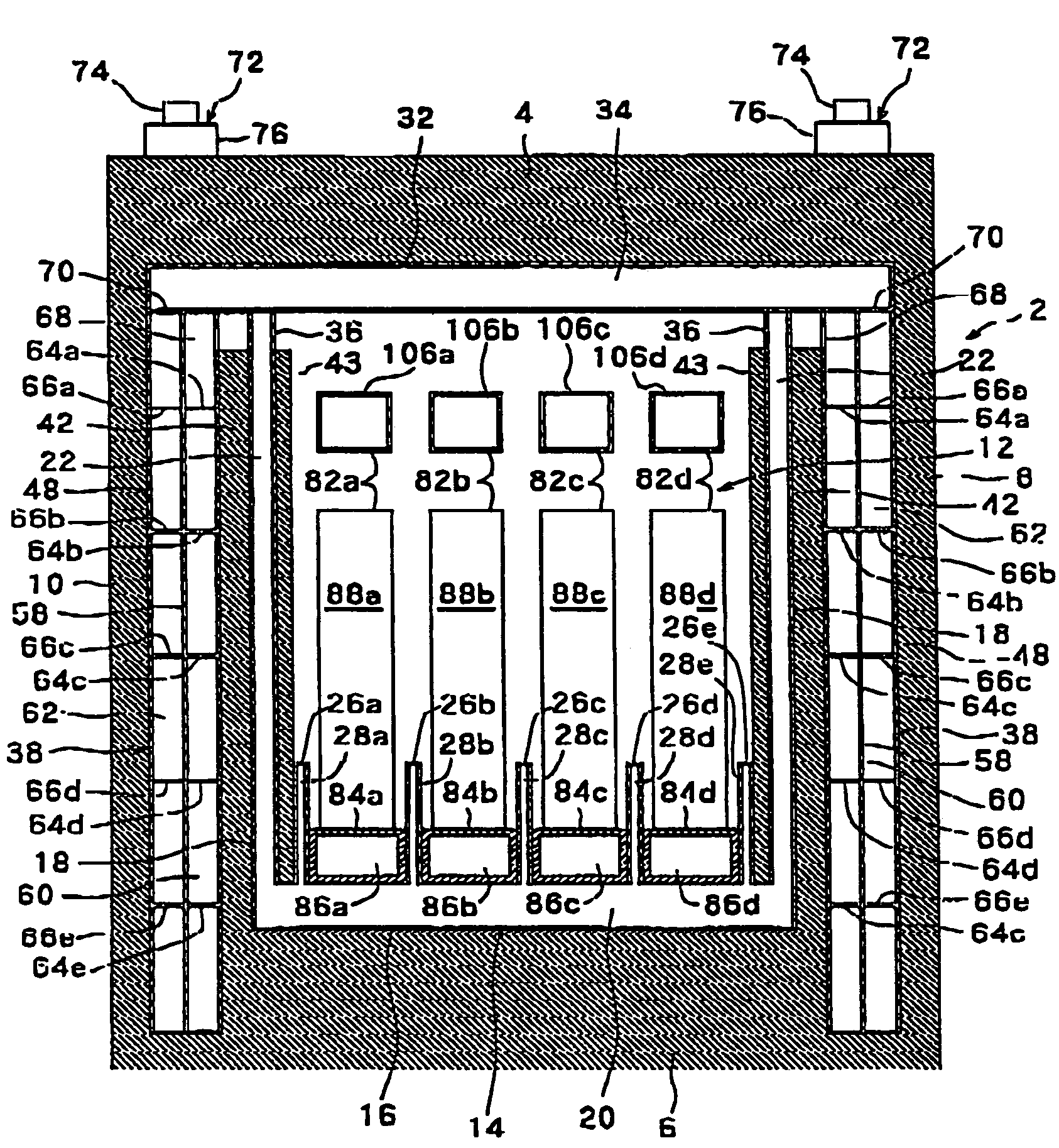
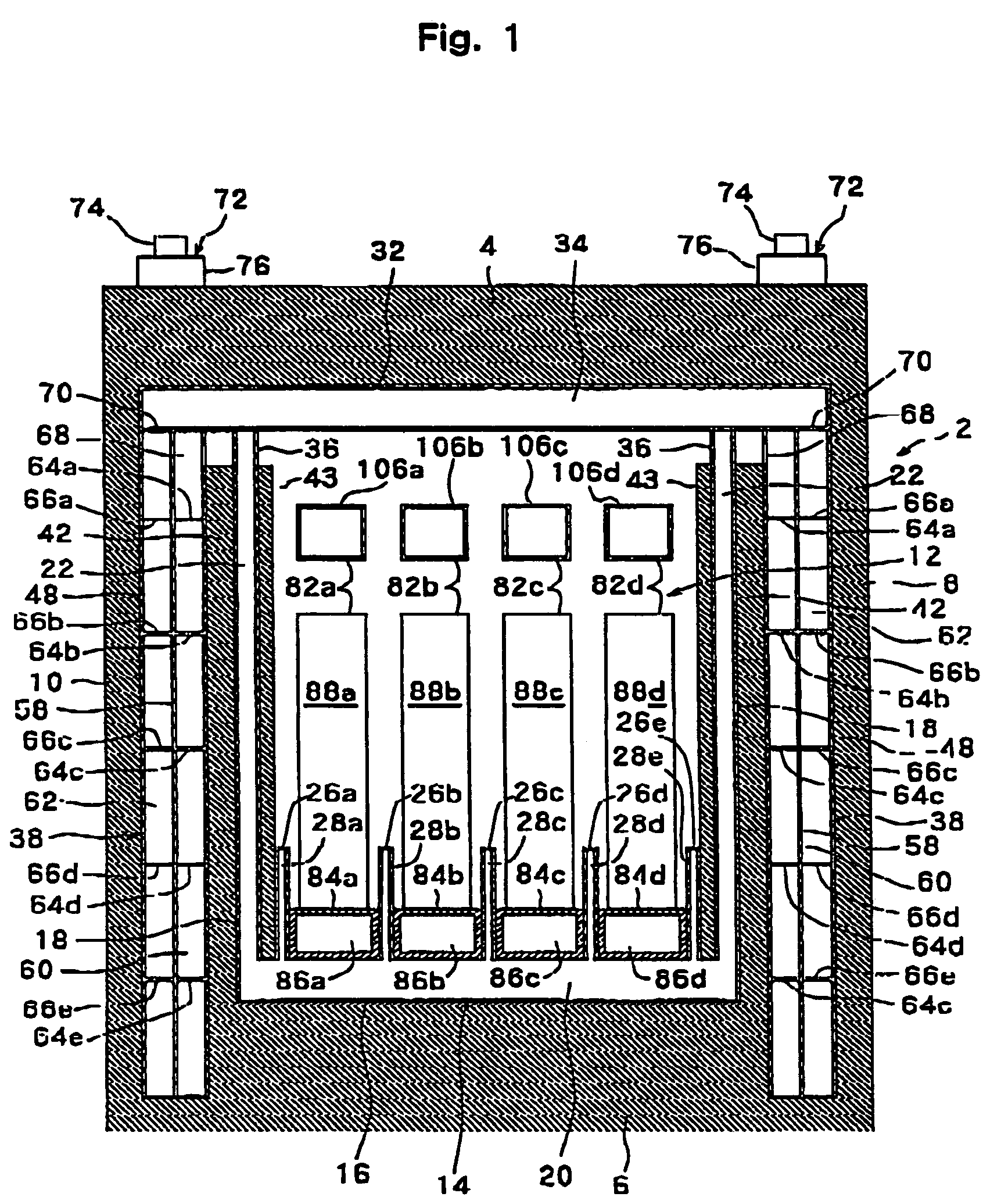
[0034]Preferred embodiments of a fuel cell assembly constructed in accordance with the present invention will now be described in further detail with reference to the accompanying drawings.

[0035]With reference to FIG. 1, the illustrated fuel cell assembly has a housing 2 which may be in a nearly rectangular parallelepipedal shape. Heat insulation walls formed from a suitable heat insulating material, i.e., an upper heat insulation wall 4, a lower heat insulation wall 6, a right heat insulation wall 8, a lest heat insulation wall 10, a front heat insulation wall (not shown), and a rear heat insulation wall (not shown), are disposed on the six wall surfaces of the housing 2. An electricity generation / combustion chamber 12 is defined in the housing 2. The front heat insulation wall and / or the rear heat insulation wall are or is mounted detachably or openably and closably. By removing or opening the front heat insulation wall and / or the rear heat insulation wall, the interior of the ele...


PUM

PropertyMeasurementUnit
temperatureaaaaaaaaaa
open porosityaaaaaaaaaa

Abstract

A fuel cell assembly has a housing defining an electricity generation / combustion chamber, and electricity generation / combustion means disposed within the housing. A fuel gas and an oxygen-containing gas are supplied to the electricity generation / combustion means, and a combustion gas formed within the electricity generation / combustion chamber is discharged from the electricity generation / combustion chamber. A heat exchanger having a first channel and a second channel is disposed on at least one surface of the housing, the combustion gas is discharged from the interior of the electricity generation / combustion chamber through the first channel of the heat exchanger, and one of the oxygen-containing gas and the fuel gas is supplied to the electricity generation / combustion means through the second channel of the heat exchanger. A plurality of electricity generation units are arranged in parallel within the housing, and each of the electricity generation units includes a cell stack constituting the electricity generation / combustion means.

Description

FIELD OF THE INVENTION[0001]This invention relates to a fuel cell assembly of the type in which electricity generation / combustion means is disposed in an electricity generation / combustion chamber defined within a housing, electricity generation and combustion are performed by supplying a fuel gas and an oxygen-containing gas to the electricity generation / combustion means, and a combustion gas is discharged from the electricity generation / combustion chamber; and an electricity generation unit which can be used in such a fuel cell assembly.DESCRIPTION OF THE PRIOR ART[0002]In recent years, various types of fuel cell power systems, such as polymer electrolyte fuel cells, phosphoric acid fuel cells, molten carbonate fuel cells, and solid electrolyte fuel cells, have been proposed as next-generation energy sources. The solid electrolyte fuel cell power systems, in particular, operate at a high temperature of 1,000° C., but have advantages, such as a high electrical efficiency and availab...

Claims


Application Information

Patent Timeline
Patent Type & Authority Patents(United States)
IPC IPC(8): H01M8/14H01M2/00H01M2/02H01M2/14H01M8/00H01M8/04H01M8/06H01M8/10H01M8/12H01M8/18H01M8/22H01M8/24
CPCH01M8/04007H01M8/04022H01M8/0625H01M8/2465H01M2008/1293Y02E60/50Y02E60/525H01M8/2425H01M8/2484H01M8/2483H01M8/0267
Inventor ONO, TAKASHITAKAHASHI, NARUTOIKEDA, MASATOSHIMARUYA, KAZUMASANISHIMURA, MICHIAKI
Owner KYOCERA CORP
Why Eureka
Try Eureka