Fluid conduit

a technology of fluid conduit and hose, which is applied in the field of conduits, can solve the problems of reducing mechanical properties, end fittings creeping and failing, and thermoplastic hoses, and achieves the effects of reducing the collapse resistance of hoses, increasing reinforcement layers, and high containmen

Active Publication Date: 2009-02-24
OCEANEERING INT SERVICES
View PDF27 Cites 18 Cited by
  • Summary
  • Abstract
  • Description
  • Claims
  • Application Information

AI Technical Summary

Benefits of technology

[0012]Thus, with a fluid conduit and / or a multi-conduit umbilical, according to either aspect of the present invention, the problems of supplying working fluids such as highly pressurised hydraulic fluids through a conduit / umbilical within the riser annulus of a drill string can be achieved and realised for the first time, in an economical and reliable manner.
[0018]Alternatively or additionally there is advantageously provided a filler material between adjacent turns and / or layers of said strand material so as to substantially eliminate any voids between adjacent strands of material. It is to be appreciated that the inclusion of voids within such a conduit structure can give rise to pressure balancing within a conduit structure which could cause failure in such a highly pressurised working environment.
[0024]Preferably there may be provided over a length of conduit (or multi conduit umbilical) differing levels of internal pressure containment and / or collapse resistance (with respect to water depth). At the top side virtually no collapse resistance is required but very high containment is essential. Thus topside the collapse-resistance of the hose may be reduced by using a hose with a thinner wall thickness, or a hose with a different construction or changing the grade of material or combinations thereof. To contain the internal pressure in the hose topside a high level of containment is required and thus the reinforcement layer may be increased by using a stronger strand material, a thicker diameter stand material, a better quality strand material and / or by increasing the number of layers of strand material or combinations thereof. On the other hand at the subsea level, low containment strength is acceptable (due to the ambient pressure found at the wellhead) but high collapse resistance is essential. Accordingly for containment purposes the reinforcement strand material strength, diameter or number of layers thereof may be reduced and stronger materials used for the collapse resistant hose and / or by using a different constructions of hose or changing the grade of materials used in the hose or combinations thereof.

Problems solved by technology

Recent deepwater sub-sea exploration has created the demand and need to place the work over umbilical within the riser annulus of the drill string and conventional thermoplastic hoses have proved to be unsuitable for a number of reasons as follows:—Temperature—Where a work over umbilical is inserted into the riser annulus the umbilical may be subjected to temperatures of up to 130° C. from the wellstream flowing through the riser core.
High temperatures significantly reduce the mechanical properties of the polymers used in standard sub-sea control hoses causing end fittings to creep and fail.
Additionally high temperatures affect the collapse resistance of the hose due to the reduction in the modulus of elasticity for the polymers used.
High external pressures significantly reduce the tensile strength and fatigue resistance of the pressure containment layer, typically an aramid fibre braided pressure containment layer, as the material is sandwiched between a core tube and an outer jacket and is subjected to significant and damaging crush loads found at the wellhead in such deep water installations.High working pressures—In order to operate the hydraulic control and chemical injection hoses at depths of up to 3000 m, where differential pressures are up to 300 bar (30 MN / m2), very high topside or ambient pressures are required, typically 1200 bar is required.
Conventional standard thermoplastic hoses using aramid fibre braided layer technology to contain the working fluid at these elevated working pressures are unsuitable due to the limitations in material technology which give rise to reductions in the operational reliability of such hoses.
Furthermore the muds used within the riser annulus create a highly corrosive, abrasive and volatile environment where conventional hose structures / hose materials are unsuitable.

Method used


Image

  • Fluid conduit
  • Fluid conduit

Examples


Embodiment Construction

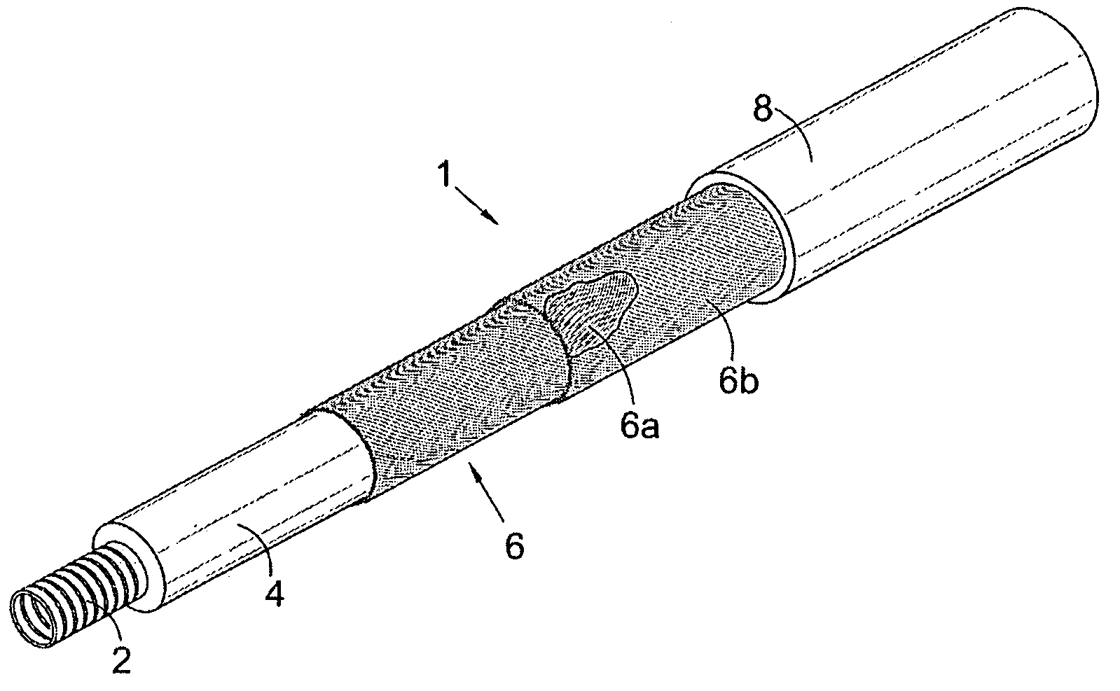
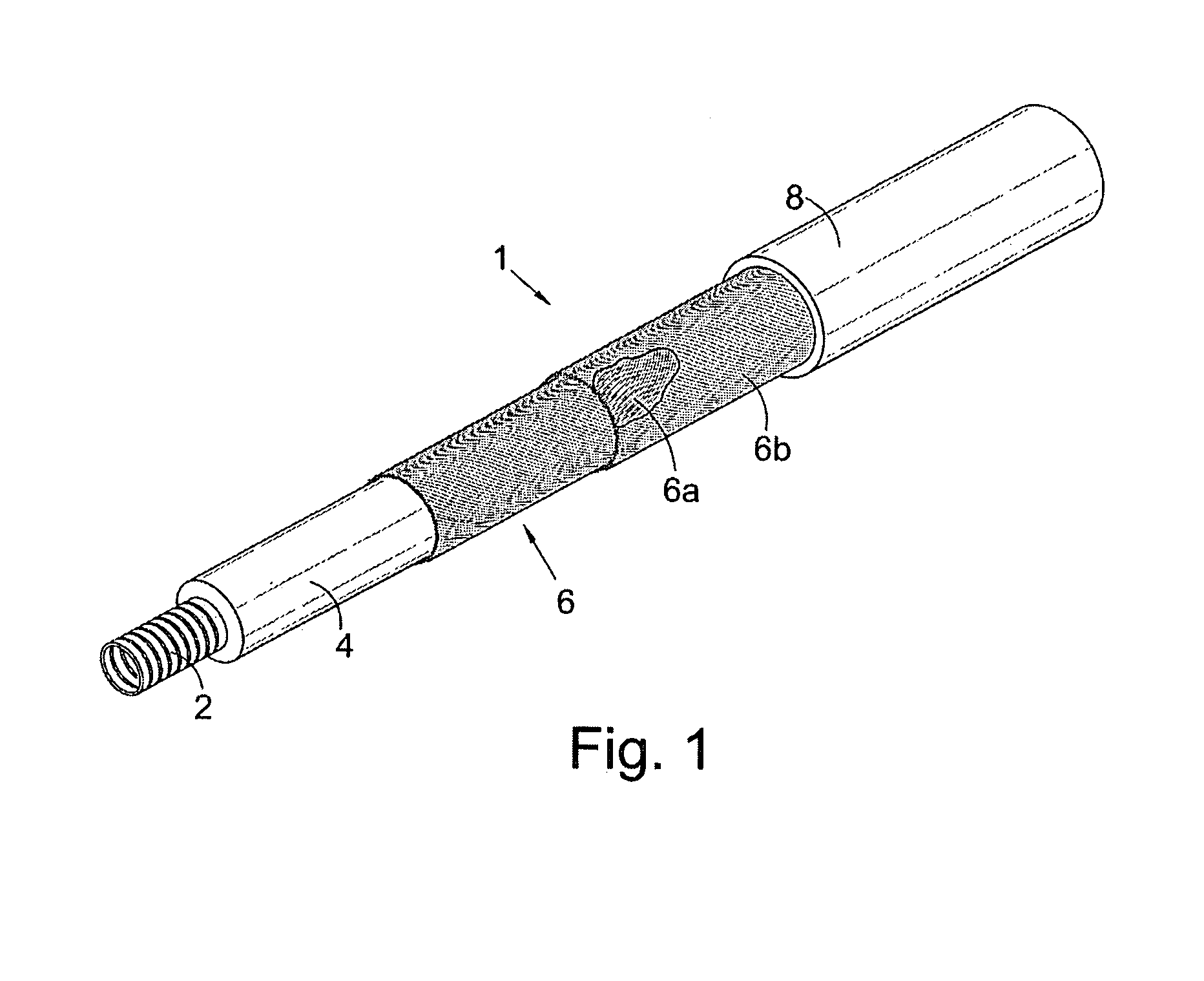
[0033]FIG. 1 shows a fluid conduit, generally indicated by reference number 1, for the transportation of working fluids, such as hydraulic fluids, to a wellhead or the like from a topside location or the like. Typically the fluid conduit would comprise one of a plurality of similar conduits arranged in a multi-conduit umbilical (not shown).

[0034]The conduit comprises an inner flexible collapse resistant hose 2 surrounded by an extruded hose liner 4 and two layers 6 of a pair of helically contra-wound high tensile steel wires 6a, 6b. Each turn of the steel wires 6a, 6b is tightly wound against, and is bonded in substantially close contact, with adjacent turns.

[0035]In more detail the inner flexible collapse resistant hose 2 comprises a metallic interlock wound carcass having an inside diameter in the range of from 3 / 16 in (4.76 mm) to ¾ in (19.05 mm).

[0036]The hose liner 4 is an extruded layer of fluoro-polymer approximately 1 mm thickness.

[0037]As shown in FIG. 1 there is provided t...


PUM


Abstract

The present invention relates to fluid conduit (1) suitable for use in the transportation of working fluids to a wellhead or the like from a topside location or the like. The fluid conduit (1) is suitable for use in a multi-conduit umbilical. The conduit comprises an inner flexible collapse resistant hose (2) surrounded by a hose liner (4), and at least one pair of helically contra-wound high tensile wires (6a, 6b). Each turn of each wire (6a, 6b) is in substantially close contact with adjacent turns thereof. A multi-conduit umbilical comprising a plurality of the fluid conduits bundled together and provided with an outer sheath is also described.

Description

RELATED APPLICATIONS[0001]The present application claims priority from British Application No. GB0322529.9 filed on Sep. 26, 2003.FIELD OF THE INVENTION[0002]The present invention relates to a conduit suitable for use in transporting fluids, particularly well control fluids and hydraulic fluids, and particularly to a fluid conduit or hose, sometimes referred to as an umbilical or a work over umbilical, for use in, for example offshore drilling environments including oil / gas exploration and production.BACKGROUND OF THE INVENTION[0003]In offshore drilling environments it is necessary to supply hydraulic fluids to the wellhead and the standard practice up until relatively recently has been to use a standard thermoplastic hydraulic sub-sea control umbilical hose for the purpose of work over control where work over operations are performed on a sub-sea wellhead using a work over riser. These standard hydraulic sub-sea control umbilical hoses are placed outside the riser from the topside ...

Claims


Application Information

Patent Timeline
Patent Type & Authority Patents(United States)
IPC IPC(8): F16L11/00F16L9/147F16L11/08
CPCF16L9/147F16L11/088F16L11/082F16L11/083F16L11/22
Inventor THOMSON, FRASER HYND
Owner OCEANEERING INT SERVICES
Why Eureka
Try Eureka