Composite free layer for stabilizing magnetoresistive head

a free layer and stabilizing technology, applied in the field of read element of a magnetoresistive head, can solve the problems of affecting the free layer, affecting the magnetic moment, and affecting the stability of the magnet, so as to reduce the undesired effect of spin transfer, maximize isw, and be stable against spin transfer induced switching

Inactive Publication Date: 2009-02-24
TDK CORPARATION
View PDF9 Cites 55 Cited by
  • Summary
  • Abstract
  • Description
  • Claims
  • Application Information

AI Technical Summary

Problems solved by technology

When a polarized electron meets a ferromagnetic film, the electron is harmed by the magnetic moments and scattered.
However, the free layer is strongly affected by electron spin transfer, which exerts a torque on its magnetization.
One of them is that the electrode connected to the free layer must be reduced in size which will cause an overheat and damage of the head.
Also the readout signal available from CIP-GMR is proportional to the MR head width, that means there is a limitation for CIP-GMR at high recording density.
However, the related art BMR spin valve is in early development, and is not in commercial use.
Further, there are related art problems with the BMR spin valve in that nano-contact shape and size controllability and stability of the domain wall must be further developed.
More specifically, rotation of the free layer magnetization direction is more difficult for a large MS and easier for a small MS.
However, there are various problems and disadvantages in the related art.
For example, but not by way of limitation, there is a problem of thermal stability, due to a high demagnetizing field.
Also, perturbation or fluctuation of the magnetic moment distribution in the free layer (i.e., sensor) generates an additional source of noise.

Method used


Image

  • Composite free layer for stabilizing magnetoresistive head
  • Composite free layer for stabilizing magnetoresistive head
  • Composite free layer for stabilizing magnetoresistive head

Examples


Embodiment Construction

[0071]Referring now to the accompanying drawings, description will be given of preferred embodiments of the invention.

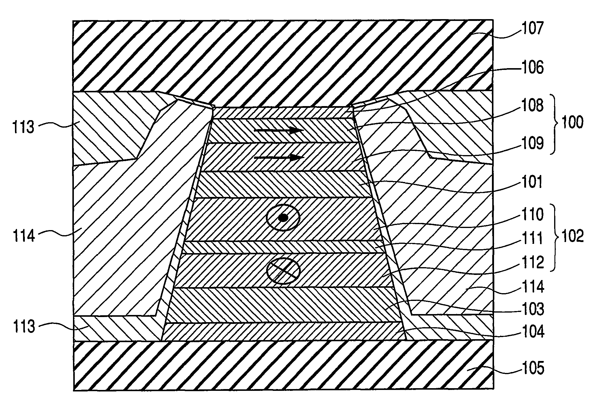
[0072]In an exemplary, non-limiting embodiment of the present invention, a novel spin valve for a magnetoresistive head having a high resistivity material is provided, resulting in an improved spin valve.

[0073]The present invention is directed to parameters D and a of equation (2), which can be optimized based on material selection for the free layer. As a result of proper material selection, head stability is improved, and a high frequency response of the head (high data rate) is achieved.

[0074]More specifically, the present invention relates to material optimization for reducing spin transfer effect in a read head to increase the dynamic response of free layer and reduce the above-described vortex effect. Co thin film is used in the free layer due to its high exchange stiffness as compared to other related art materials used in heads (such as Fe, Ni, CoFe and Ni80F...


PUM

PropertyMeasurementUnit
thicknessaaaaaaaaaa
thicknessaaaaaaaaaa
thicknessaaaaaaaaaa

Abstract

A magnetoresistive read head includes a spin valve having at least one free layer spaced apart from at least one pinned layer by a spacer. The free layer includes a cobalt compound as a thin film including at least one of Co—X, CoFe—X and CoNi—X, where X is an element from the lanthanoid family (a 4-f element). The content of Co is higher than 80 percent, and the content of the lanthanoid element is less than 10 percent. The film may comprise the entire free layer, or be positioned adjacent to one or more conventional free layer films. The pinned layer is a conventional single layer, or a synthetic multi-layered structure having a spacer between sub-layers. Because the spin valve structure has a high exchange stiffness and damping factor, spin transfer effect is reduced and a high-speed dynamic response is provided.

Description

TECHNICAL FIELD[0001]The present invention relates to the field of a read element of a magnetoresistive (MR) head. More specifically, the present invention relates to a spin valve of an MR read element having a free layer that includes a material having a high exchange stiffness and a high damping factor.BACKGROUND ART[0002]In the related art magnetic recording technology such as hard disk drives, a head is equipped with a reader and a writer. The reader and writer have separate functions and operate independently of one another, with no interaction therebetween.[0003]FIGS. 1(a) and (b) illustrate related art magnetic recording schemes. A recording medium 1 having a plurality of bits 3 and a track width 5 has a magnetization parallel to the plane of the recording media. As a result, a magnetic flux is generated at the boundaries between the bits 3. This is also commonly referred to as “longitudinal magnetic recording”.[0004]Information is written to the recording medium 1 by an indu...

Claims


Application Information

Patent Timeline
Patent Type & Authority Patents(United States)
IPC IPC(8): G11B5/39G01R33/09G11B5/00
CPCB82Y10/00B82Y25/00G01R33/093G11B5/3912G11B5/3932G11B2005/0029G11B2005/3996
Inventor SBIAA, RACHIDSATO, ISAMU
Owner TDK CORPARATION
Why Eureka
Try Eureka