Power supply voltage control apparatus

a power supply voltage and control apparatus technology, applied in the direction of dc-dc conversion, power conversion systems, oscillation generators, etc., can solve problems such as circuit operation errors, power supply voltage control apparatuses, and circuit operation errors

Inactive Publication Date: 2009-03-10
SOCIONEXT INC
View PDF14 Cites 45 Cited by
  • Summary
  • Abstract
  • Description
  • Claims
  • Application Information

AI Technical Summary

Benefits of technology

[0018]It is therefore an object of the present invention to provide a power supply voltage control apparatus capable of arbitrarily setting a clock period setting margin according to a system clock frequency, and converging a power supply voltage to a minimum power supply voltage for normal operation in a short period of time without errors in internal circuit operation in response to switching of a plurality of system clock frequencies

Problems solved by technology

However, when the accuracy of power supply voltage setting is coarse, or, when a power supply voltage setting circuit is temperature dependant, errors in circuit operation may occur as a result of timing errors by reducing power supply voltage too low.
Further, there are also cases where timing errors may occur as a result of decrease of the driving performance of a MOS transistor due to temperature fluctuation, and may lead errors in circuit operation.
However, the conventional power supply voltage control apparatuses have the following problems.
However, the power supply voltage control circuit takes a certain amount of time from when the power supply voltage is applied and a lag of phase or frequency between the clock output signal of the voltage control oscillator circuit and the reference clock signal is detected till when control actually operates and corrected power supply voltage is applied, and therefore the power supply voltage fluctuates.
Therefore, the first problem is that, though it is necessary to change a setting margin of a period of a clock signal outputted from the voltage control oscillator circuit or a delay value generated by the voltage control delay circuit and a period of the reference clock signal with respect to the minimum power supply voltage corresponding to the system clock frequency, Patent Documents 1, 2 and 4 cannot be compatible with this, since the setting margin is fixed.
However, the input signal generating circuit is shared with a monitor circuit having various delay values compatible with functions of the semiconductor circuit, and does not function for changing the clock period setting margin according to the above-described system clock frequency.
Further, the input signal generating circuit is configured with a PLL (Phase-Locked Loop) and selector, and therefore the problem arises that circuit scale increases substantially.
The apparatus of Patent Document 4 sets the level control signal so that the initial value becomes a start-up minimum power supply voltage, and, upon start-up of the semiconductor circuit, time for the power supply voltage to converge to an optimum value can be reduced However, the setting of the level control signal is only considered upon start-up of the power supply, and therefore the apparatus cannot be compatible with switching of a plurality of system clock frequencies.
Namely, the second problem is that, when the system clock frequency is changed from a high frequency to a low frequency, first, the system clock frequency changes, and the power supply voltage is adjusted to be small according to this frequency, but, when the change in frequency is large, the change in power supply voltage also becomes large, and it takes a great deal of time to converge the power supply to the minimum power supply voltage for normal operation.
Further, when the system clock frequency is changed from a low frequency to a high frequency, if the system clock frequency increases before the power supply voltage increases, a problem of inviting errors in the internal circuit operation arises.

Method used


Image

  • Power supply voltage control apparatus
  • Power supply voltage control apparatus
  • Power supply voltage control apparatus

Examples


embodiment 1

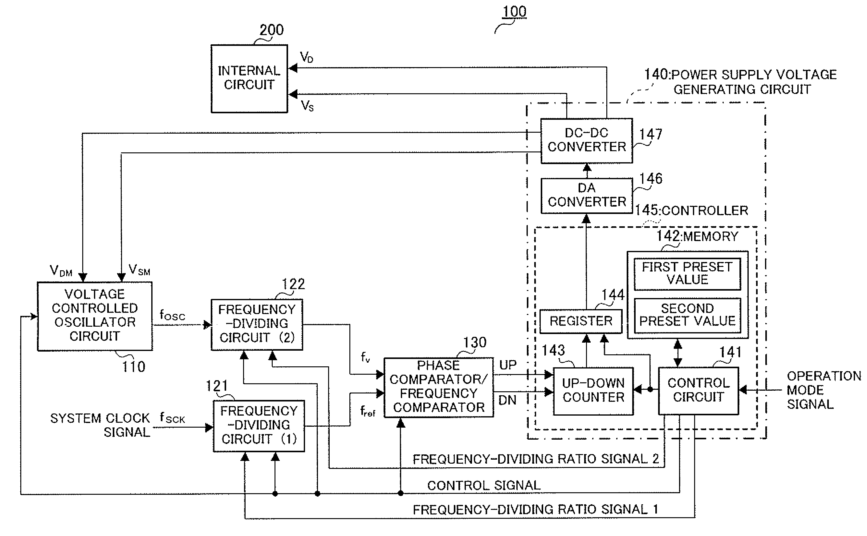
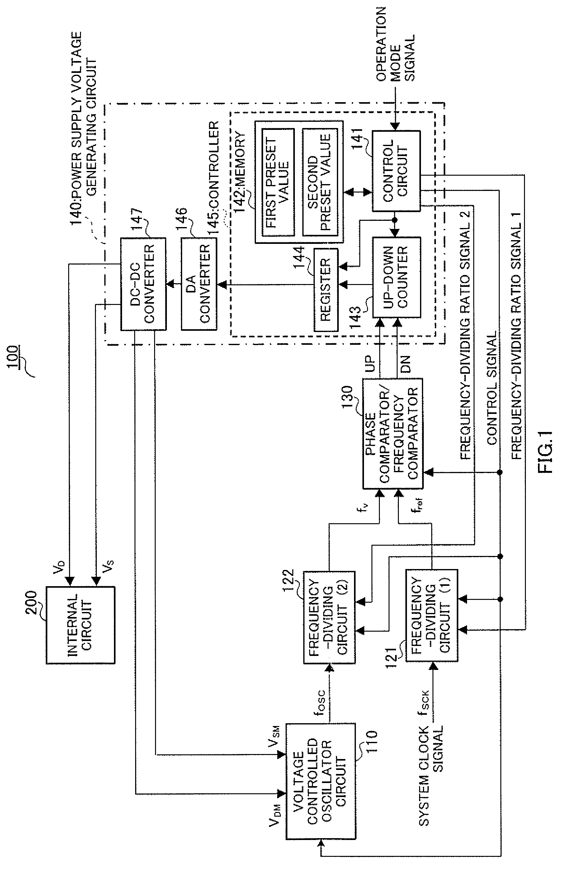
[0038]FIG. 1 is a circuit diagram showing a configuration of the power supply voltage control apparatus according to embodiment 1 of the present invention. This embodiment is an example applied to the power supply voltage control apparatus supplying a predetermined power supply voltage to an internal circuit having a plurality of MOS transistors.

[0039]In FIG. 1, reference numeral 100 is a power supply voltage control apparatus, and reference numeral 200 is an internal circuit that operates by receiving the supply of power supply voltages VD and VS from power supply voltage control apparatus 100.

[0040]Power supply voltage control apparatus 100 adopts a configuration having: voltage control oscillator circuit 110 that generates a clock signal; frequency-dividing circuit 121 (frequency-dividing circuit 1>) that frequency-divides system clock signal fsck; frequency-dividing circuit 122 (frequency-dividing circuit 2>) that frequency-divides clock output signal fosc of voltage control osc...

embodiment 2

[0081]FIG. 8 is a circuit diagram showing a configuration of the power supply voltage control apparatus according to Embodiment 2 of the present invention. This embodiment is an example of the case where a plurality of internal circuit blocks exist and power supply voltage control is carried out for each internal circuit block.

[0082]FIG. 8 shows the configuration where internal circuit block 1 and internal circuit block 2 are independently controlled by power supply voltage control circuit 1 and power supply voltage control circuit 2, respectively, and operation mode controllers control power supply voltage control circuits 1 and 2 by operation mode signals.

[0083]The circuit configuration and circuit operation of each power supply voltage control circuit is exactly the same as described above, and therefore explanation is omitted.

embodiment 3

[0084]FIG. 9 is a circuit diagram showing a configuration of the power supply voltage control apparatus according to Embodiment 3 of the present invention. This embodiment is an example of a circuit configuration where a plurality of internal circuit blocks exist, and power supply voltages of a plurality of internal circuit blocks (two in this embodiment) are controlled with a single power supply voltage control circuit. Components that are identical with FIG. 1 will be assigned the same reference numerals without description of the duplicated parts.

[0085]In FIG. 9 reference numeral 300 is a power supply voltage control apparatus, and reference numeral 400 is an internal circuit block 1> operating by receiving the supply of power supply voltages VD1 and VS1 from power supply voltage control apparatus 300, and an internal circuit block2> operating by receiving the supply of power supply voltages VD2 and VS2.

[0086]Power supply voltage control apparatus 300 adopts a configuration havin...


PUM


Abstract

A power supply voltage control apparatus capable of freely setting a clock period setting margin according to a system clock frequency, and capable of converging power supply voltage to minimum power supply voltage where normal operation is possible in a short period of time without errors in operation of internal circuits in response to changes in the system clock frequency is provided. Power supply voltage control apparatus 100 is provided with frequency-dividing circuit 121 that frequency-divides the system clock at frequency-dividing ratio 1, frequency-dividing circuit 122 that frequency-divides the output of voltage control oscillator circuit 110 at frequency-dividing ratio 2, phase comparator / frequency comparator 130 that carries out phase comparison / frequency comparison on the respective output signals of frequency-dividing circuits 121 and 122, and controller 145. Frequency-dividing ratios of frequency-dividing circuits 121 and 122 are set by control circuit 141 according to an operation mode signal corresponding to the system clock frequency.

Description

BACKGROUND OF THE INVENTION[0001]1. Field of the Invention[0002]The present invention relates to a power supply voltage control apparatus that controls power supply voltage of a semiconductor integrated circuit apparatus such as an LSI (Large Scale Integration)[0003]2. Description of the Related Art[0004]In recent years, as important methods for reducing power consumption of the semiconductor integrated circuit, methods of changing power supply voltage according to clock frequencies are well-known. However, when the accuracy of power supply voltage setting is coarse, or, when a power supply voltage setting circuit is temperature dependant, errors in circuit operation may occur as a result of timing errors by reducing power supply voltage too low. Further, there are also cases where timing errors may occur as a result of decrease of the driving performance of a MOS transistor due to temperature fluctuation, and may lead errors in circuit operation.[0005]With regards to this problem, ...

Claims


Application Information

Patent Timeline
Patent Type & Authority Patents(United States)
IPC IPC(8): H03L7/06
CPCH02M3/157G05F1/56H02M3/155H03L7/06
Inventor ITO, MINORU
Owner SOCIONEXT INC
Why Eureka
Try Eureka