Optical recording and reading equipment
a technology of optical applied in the field of data recording and reading equipment, can solve the problems of limited optical efficiency, increased manufacturing cost, complicated system design, etc., and achieve the effect of reducing laser noise, reducing laser noise, and large laser nois
- Summary
- Abstract
- Description
- Claims
- Application Information
AI Technical Summary
Benefits of technology
Problems solved by technology
Method used
Image
Examples
first embodiment
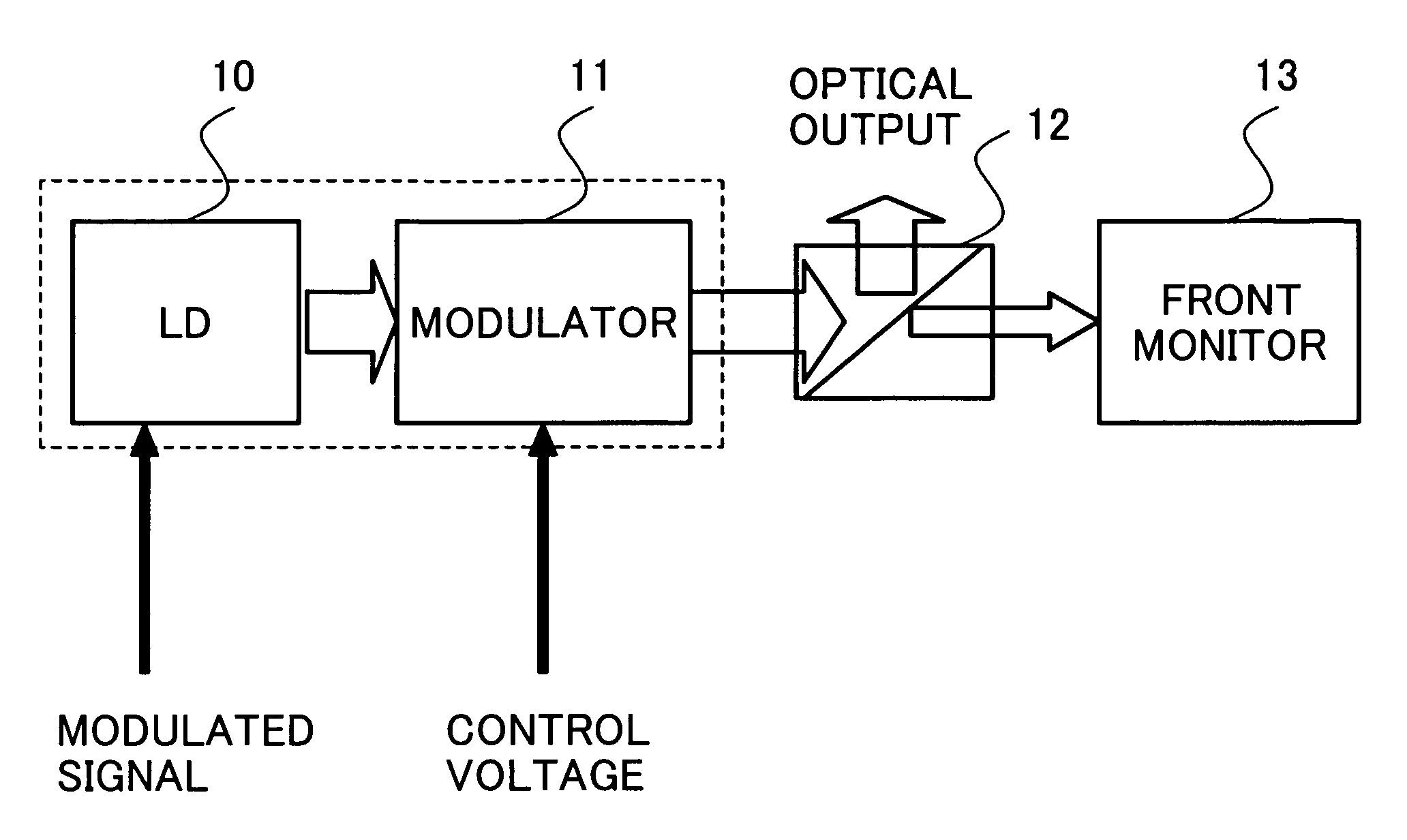
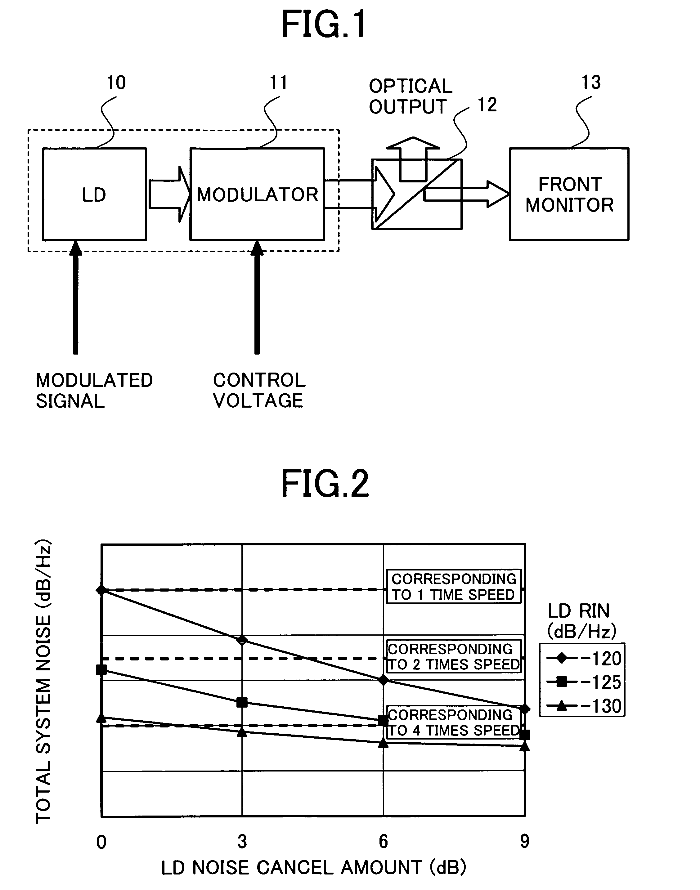
[0037]At first, a description will be made for an optical disk system that uses a laser disposed so as to precede a modulator in the first embodiment with reference to FIG. 1. The value of the noise level (RIN) is lowered up to a level required by the system when in reading. At that time, a laser output power with which the required RIN value is reached is set and the attenuation value of the modulator disposed preceding the laser is controlled with a voltage so that the attenuation reaches the specified 0.35 mW on the surface of the subject disk. In the BD standard, correspondence to two-layer disks is also ruled. The reading power of the 2-layer disks is set at 0.7 mW. More concretely, in this semiconductor laser element, the beam output from the beam source is inputted to the modulator 11 disposed adjacently. When in recording and erasing, no voltage is applied to the modulator 11 so that the beam passes through the modulator 11 as much as possible.
[0038]When in reading, a voltag...
second embodiment
[0039]FIG. 9 shows the second embodiment. Basically, the same items as those in the first embodiment will be omitted here. In this second embodiment, a semiconductor chip in which a modulator and an LD are integrated is used. This is only a difference from the first embodiment. In case an electro absorption type modulator is used, the laser can also be integrated in the semiconductor chip as to be described below. This integration is effective to reduce the semiconductor chip in size significantly. Slim-sized disk drives have been required to be developed for optical disks of PCs, particularly for lap-top PCs. Those compact-sized disk drives will thus come to be reduced in size more and more indispensably to enable compatibility among CD, DVD, and BD. In case the modulator is to be installed separately in the semiconductor chip, the modulator package should also be integrated in the semiconductor chip so as to enable the chip to be manufactured easily.
[0040]In this case, the laser n...
third embodiment
[0041]Next, the third embodiment of the present invention will be described with reference to FIGS. 10 through 12. In this third embodiment, high speed APC is realized and the laser power is actually controlled by a modulator.
[0042]At first, the APC will be described briefly. FIG. 10 shows a conventional configuration of the APC. The APC is roughly divided into two portions; so-called reading power APC performed when reading data from the subject optical disk and writing APC performed when writing data into the optical disk. The reading APC is performed to keep the reading laser power at 0.35 mW in a state of high frequency superposition (400 MHz for BD). The writing APC is performed to fix the writing laser power while data is recorded with waveforms referred to as strategy, which is specific to optical disks.
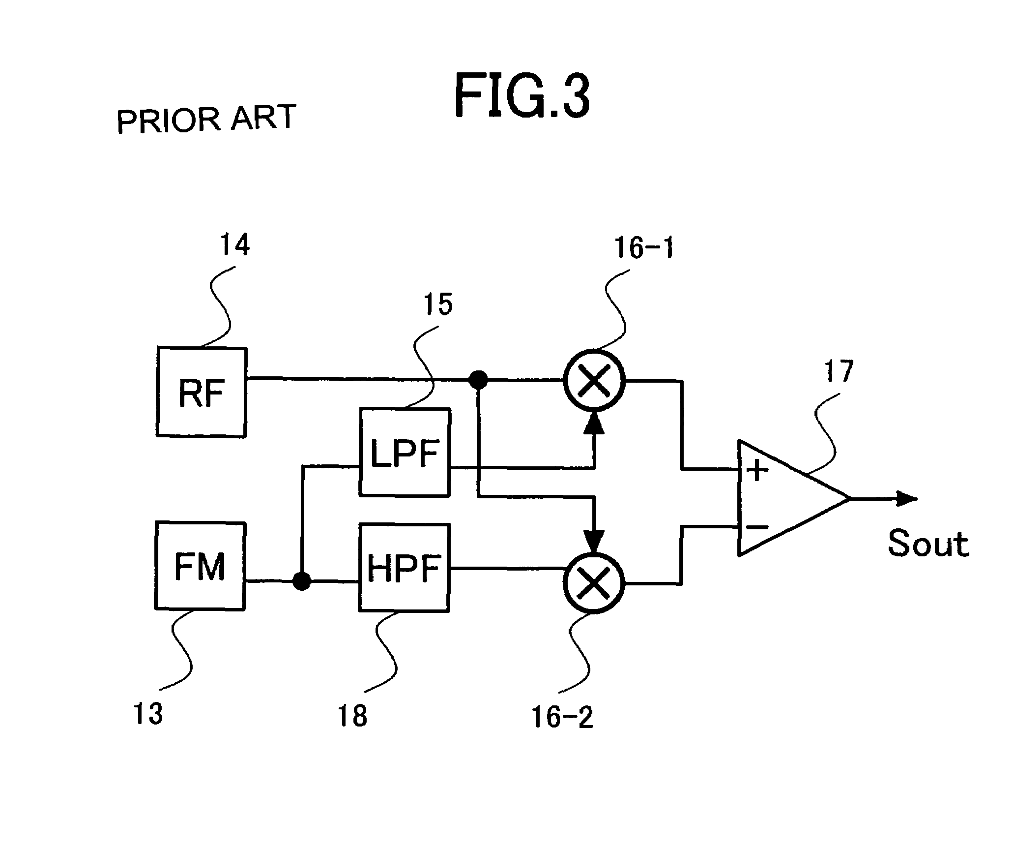
[0043]Those APC operations are realized by monitoring the optical output power at a front monitor 13 as shown in FIG. 10 and feeding back the output power to an LD driver. The...
PUM
| Property | Measurement | Unit |
|---|---|---|
| wavelength | aaaaa | aaaaa |
| wavelengths | aaaaa | aaaaa |
| wavelengths | aaaaa | aaaaa |
Abstract
Description
Claims
Application Information
 - R&D
- Intellectual Property
- Life Sciences
- Materials
- Tech Scout
- Unparalleled Data Quality
- Higher Quality Content
- 60% Fewer Hallucinations
Browse by: Latest US Patents, China's latest patents, Technical Efficacy Thesaurus, Application Domain, Technology Topic, Popular Technical Reports.
© 2025 PatSnap. All rights reserved.Legal|Privacy policy|Modern Slavery Act Transparency Statement|Sitemap|About US| Contact US: help@patsnap.com


