Method of fabricating one-way transparent optical system
a transparent optical system and one-way technology, applied in the direction of liquid/solution decomposition chemical coating, superimposed coating process, instruments, etc., can solve the problems of reducing the luminous efficiency and brightness of the display, and achieve high brightness, prevent dazzling effect and contrast degradation, and high brightness
- Summary
- Abstract
- Description
- Claims
- Application Information
AI Technical Summary
Benefits of technology
Problems solved by technology
Method used
Image
Examples
first embodiment
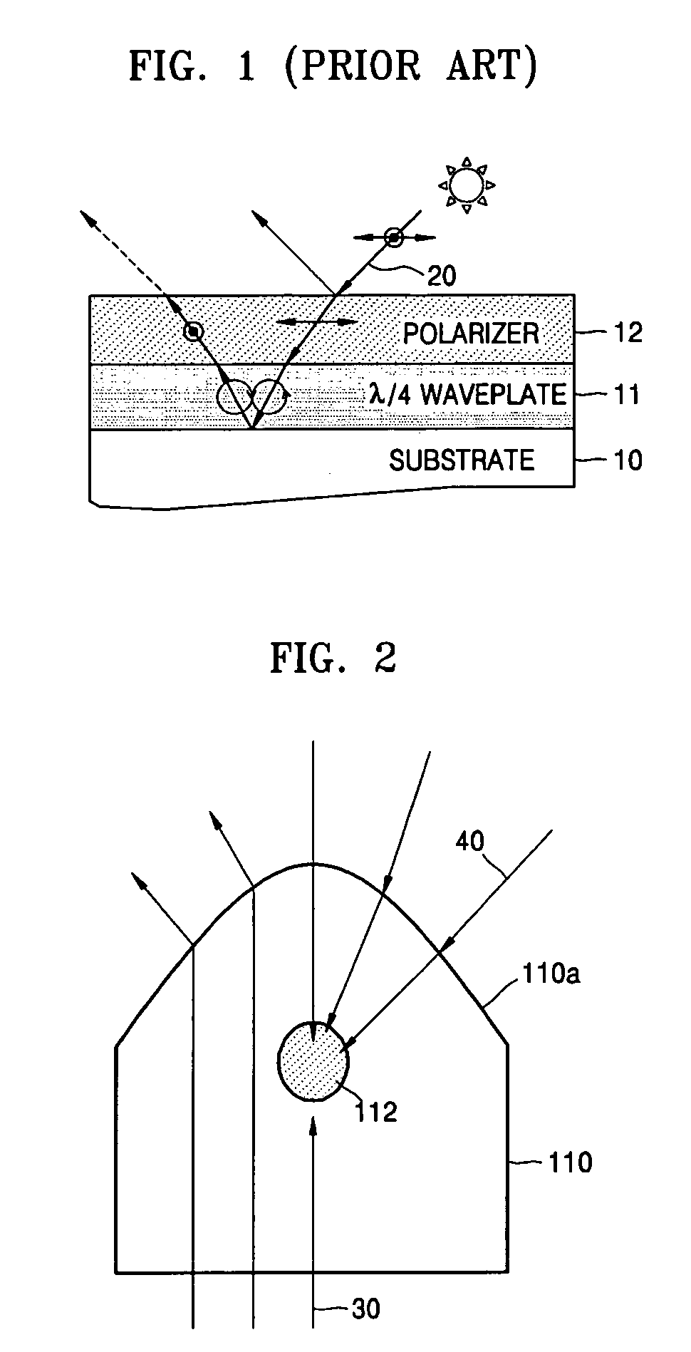
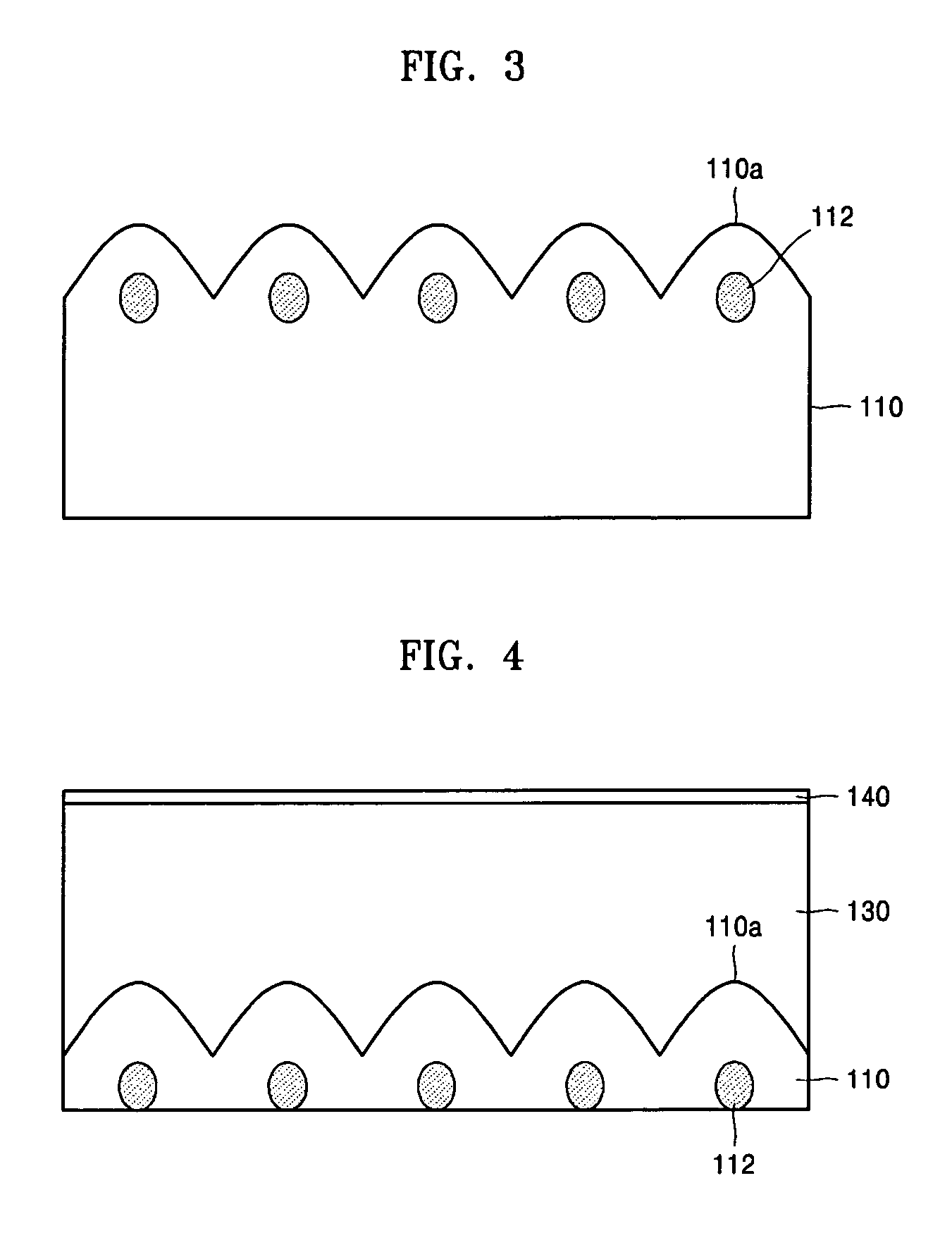
[0033]FIG. 3 illustrates a one-way transparent optical system according to the present invention, namely a reflection and dazzling preventive layer formed by two-dimensionally arranging the one-way transparent optical systems of FIG. 2. As described above, external light 40 is refracted by the convex lens-shaped projecting structures 110a into the light absorbing materials 112 and thereby absorbed, while nearly all of the internal light 30 passes through the light absorbing materials 112. The one-way transparent optical system with this simple configuration can absorb almost 100% of external light while transmitting most internal light. When the one-way transparent optical system is used in a display device, the brightness of the display device can be increased to more than twice the brightness of a conventional display. The display device also suffers little dazzling effect due to reflected light rays.
[0034]The projecting structures 110a having a micrometer diameter (e.g., of 0.1 t...
second embodiment
[0035]FIG. 4 illustrates a one-way transparent optical system according to the present invention. Referring to FIG. 4, the one-way transparent optical system includes a transparent optical material 110 having a plurality of projecting structures 110a formed on the top surface thereof, light absorbing materials 112 located near focal regions corresponding to the plurality of projecting structures 110a, a light-transmissive layer 130 disposed on the plurality of projecting structures 110a, and an anti-reflective coating 140 formed on the surface of the light transmissive layer 130. The light transmissive layer 130 preferably has a refractive index that is lower than that of a transparent material of the projecting structure 110a so that the projecting structures 110a refract incident light rays into the light absorbing materials 112. The anti-reflective coating 140 is used to almost eliminate reflections on the surface of the light transmissive layer 130. Most of the incident external...
third embodiment
[0037]FIG. 5B illustrates a one-way transparent optical system embodiment according to the present invention including a plurality of bead-shaped light absorbing elements 120 shown in FIG. 5A. The bead-shaped light absorbing elements 120 are dispersed over a transparent optical material 110 such as a transparent film and then emulsion polymerization of a coating material (not shown) such as MMA is carried out to fix the plurality of light absorbing elements 120 onto the transparent optical material 110. To accomplish this, a coating material such as MMA is interposed between the light absorbing element 120 and the transparent optical material 110. During the emulsion polymerization, a 1 to 5 wt % of crosslinking agent may be used to prevent expansion of the light absorbing element 120 when the light absorbing element 120 is dispersed into the coating material. Since the shell 122 of the light absorbing element 120, the transparent optical material 110, and the coating material have ...
PUM
| Property | Measurement | Unit |
|---|---|---|
| transparent | aaaaa | aaaaa |
| diameter | aaaaa | aaaaa |
| diameter | aaaaa | aaaaa |
Abstract
Description
Claims
Application Information
 - R&D
- Intellectual Property
- Life Sciences
- Materials
- Tech Scout
- Unparalleled Data Quality
- Higher Quality Content
- 60% Fewer Hallucinations
Browse by: Latest US Patents, China's latest patents, Technical Efficacy Thesaurus, Application Domain, Technology Topic, Popular Technical Reports.
© 2025 PatSnap. All rights reserved.Legal|Privacy policy|Modern Slavery Act Transparency Statement|Sitemap|About US| Contact US: help@patsnap.com


