
Direct radio frequency generation using power digital-to-analog conversion

a technology of direct radio frequency generation and digital-to-analog conversion, which is applied in the direction of digital-to-analog convertors, multiple carrier systems, instruments, etc., can solve the problems of high nonlinearity of power amplifiers, distortion, and upconverters suffering from similar nonlinearity effects

Inactive Publication Date: 2009-03-17
LOCKHEED MARTIN CORP
View PDF9 Cites 65 Cited by
  • Summary
  • Abstract
  • Description
  • Claims
  • Application Information

AI Technical Summary

Benefits of technology

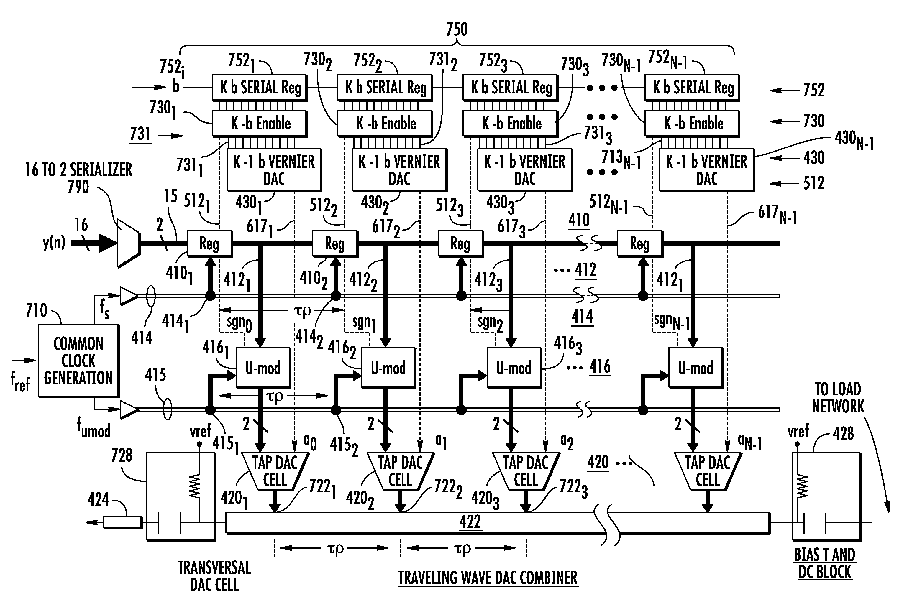
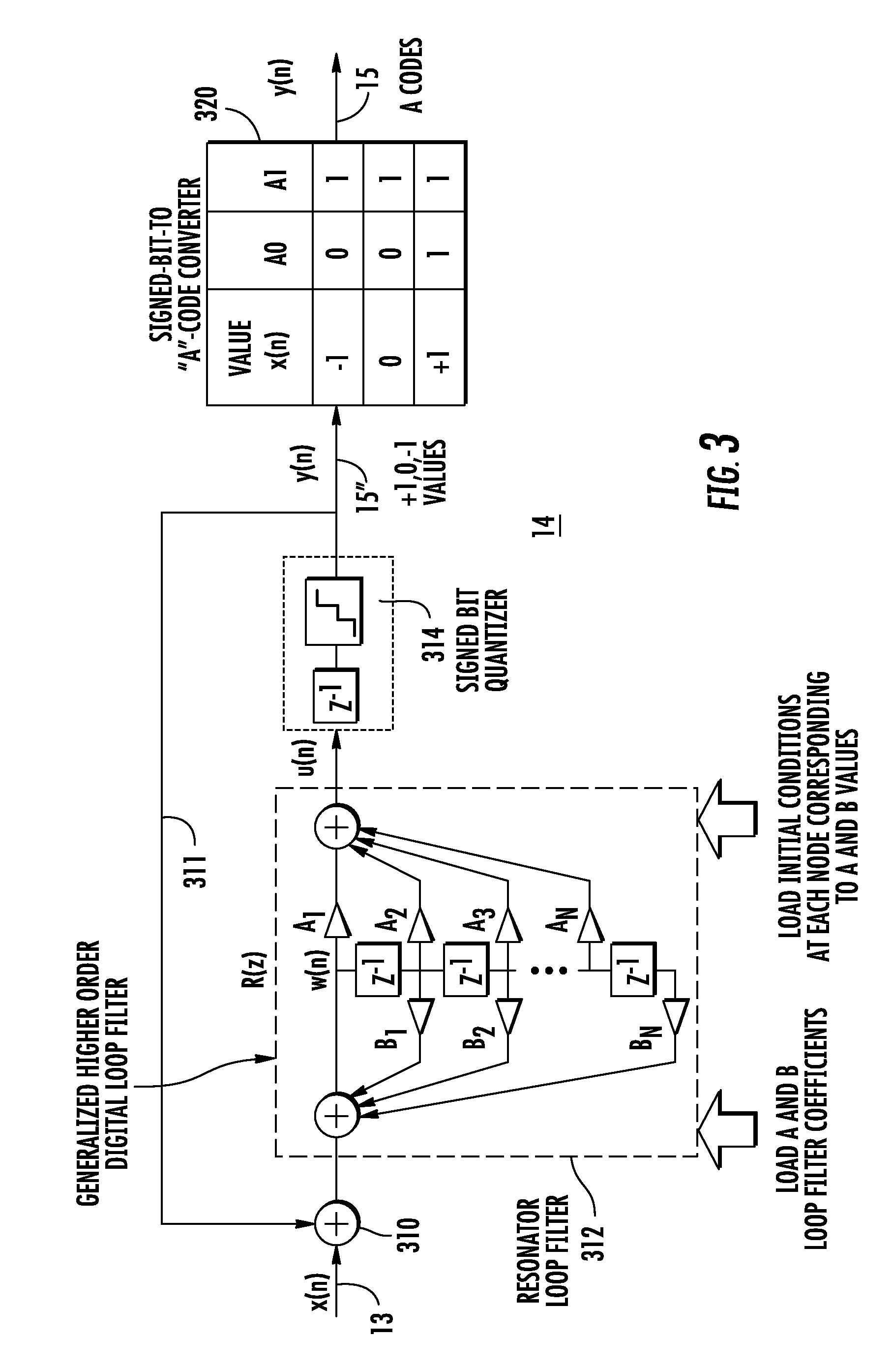
[0012]A method according to another aspect of the invention is for generating radio-frequency signals from first digital signals which represent the instantaneous amplitude of the desired radio-frequency signals. The method comprises the steps of encoding the first digital signals with Sigma-Delta encoding to thereby produce Sigma-Delta encoded signals, and delaying the bits of the Sigma-Delta encoded signals to thereby produce a plurality of differently delayed bits. The delayed bits are converted into a plurality of currents constituting a set of currents. The currents of the set are summed to produce the desired radio-frequency signals. In an especially advantageous mode of the method, the individual currents of the set of currents are weighted according to predetermined amplitude and phase representing a coefficient of a filter. In another advantageous mode of this method, the step of delaying the bits of the Sigma-Delta encoded signals comprises the step of applying the bits of the Sigma...

Problems solved by technology

This process often undesirably results in the production of spurious signals, which in turn requires additional filtering for reducing the amplitude of the spurious signal without significantly affecting the desired signals.
The power amplifier tends to be highly nonlinear when operated efficiently (that is, near saturation), and consequently tends to produce distortion when used for multicarrier applications.
Upconverters suffer from similar nonlinearity effects.
In the transmission of signals that include multiple combined signals, such as a plurality of independent channels, modulation techniques with amplitude modulation or both amplitude and phase modulation such as multibit Quadrature Amplitude Modulation (QAM) waveforms, and signals that contain multiple simultaneous beams in the context of phased array antennas, the distortion of the heavily saturated amplifiers adds unwanted components to the transmitted signals.
These intermodulation products may prevent proper system operation.
This error limits the amount of information which can be transmitted through the channel.
This is an effective solution, but is inefficient in terms of power consumption, and can also be expensive.
All of these techniques suffer from narrow bandwidth over which distortion cancellation is effective.
Additionally, these schemes may be adversely affected by environmental factors such as temperature, which may cause them to fall out of alignment.
These systems are complex and tend to be limited in the spectral purity of their output signals.
The DAC converters are subject to amplitude and time errors in producing the reconstruction of the desired RF signals, thereby distorting the single or multiple carriers.
The combined effect of the DDS chain limits its utility for generating signals without loss of information.
In practice, the predistortion signals produced by DDS systems are limited both by the quality of the DAC in the DDS and by the effectiveness of the predistortion technique itself.
While the digital algorithm provides a higher degree of freedom than does an analog system, the digital prediction algorithm or system never fully matches the amplifier distortion and often gives less improvement than might be desired.

Method used


Image

  • Direct radio frequency generation using power digital-to-analog conversion
  • Direct radio frequency generation using power digital-to-analog conversion
  • Direct radio frequency generation using power digital-to-analog conversion

Examples


Embodiment Construction

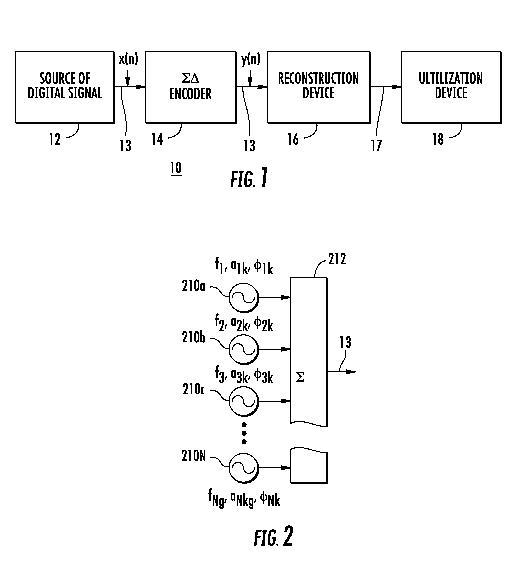
[0030]FIG. 1 is a simplified block diagram illustrating a system 10 according to an aspect of the invention. In FIG. 1, a source 12 produces digital signal time sample of the desired transmit signals from waveform controlling parameters at a given sampling or data rate and with values represented with high bit resolution. Thus, multiple simultaneous or arbitrary signals representing instantaneous amplitude of the desired radio-frequency signals are produced and are represented with sufficient precision to enable the digital signal word round-off error effects to be negligible. When a high enough sampling rate is used the RF frequency is represented directly, including its carrier frequency within the first order Nyquist band, which is between 0 Hz and ½ the sampling frequency. Also a lower actual frequency may be represented when the transmit carrier frequency exceeds ½ of the sampling frequency, in conjunction with higher order Nyquist modes of operation. The digital signals from s...


PUM


Abstract

An RF signal source receives wideband digital signals representing the instantaneous amplitude of the desired RF, and ΣΔ converts to ternary ΣΔ signals. The ternary ΣΔ signals are delayed in a transversal filter and the delayed signals are converted to currents for application to a traveling-wave summer for producing the desired RF. The traveling-wave summer may be a transmission line. The currents may be weighted with a filter response in order to limit the bandwidth of the RF signals. The RF may be coupled out through an antialiasing filter. The digital clocks may be delayed to correspond with the delays of the combiner, to impart directionality to the summed signals.

Description

FIELD OF THE INVENTION[0001]This invention relates to the generation of radio-frequency signals, and more particularly to direct generation of radio-frequency signals from digital signals.BACKGROUND OF THE INVENTION[0002]It is frequently desirable to generate radio-frequency electronic signals for various signaling, sensing and communications purposes. When radio-frequency (RF) electromagnetic signals must be transmitted, it is often necessary to transmit high power so as to easily overcome distance-related and other losses.[0003]In the past, the term “radio frequencies” was interpreted to mean a limited range of frequencies, such as, for example, the range extending from about 20 KHz to 2 MHz. Those skilled in the art know that “radio” frequencies as now understood extends over the entire frequency spectrum, including those frequencies in the “microwave” and “millimeter-wave” regions, and up to light-wave frequencies. Many of these frequencies are very important for commercial purp...

Claims


Application Information

Patent Timeline
IPC IPC(8): H03M3/00
CPCH04L27/36H03M3/504H03M1/747H03M1/1061H03M7/3026H03M7/3042H03M3/41
Inventor PELLON, LEOPOLD E.
Owner LOCKHEED MARTIN CORP
Learn More