Signal processing for a Sagnac interferometer

a technology of interferometer and signal processing, which is applied in the field of closed loop fiber optic gyroscope, can solve the problems of acousto-optic modulator, reaches the limit of its capability, and the use of pure frequency-shifting devices such as acousto-optic modulators, and achieves the effect of speeding up the signal processing of the rotation-rate feedback phase-difference component signal

Active Publication Date: 2009-03-17
BERGH RALPH A
View PDF7 Cites 7 Cited by
  • Summary
  • Abstract
  • Description
  • Claims
  • Application Information

AI Technical Summary

Benefits of technology

[0039]An object of the present invention is the provision of an improved closed loop fiber optic gyroscope having improved performance characteristics.
[0045]In another aspect of the present invention, the control loops are digitized producing a digital rotation-rate digital value, and a digital calibration signal that may be processed by a simple dividing process to produce rotation rate output for external use.
[0046]In another aspect of the present invention, two filters are used in the first feedback loop to speed up the signal processing of the rotation-rate feedback phase-difference component signal.

Problems solved by technology

Use of a pure frequency-shifting device, such as the acousto-optic modulators, is simple in principle, but difficult in practice.
The difficulty in implementing the frequency shifter approach led to reconsideration of closing the loop using a phase modulator.
A phase modulator can generate a phase ramp for a short period of time, but it then reaches the limit of its capability.
A problem with phase modulators is that each phase modulator produces a slightly different phase modulation for a given electronic drive signal.
This leads to an inadequate knowledge of the phase shifts that are imparted to the counter-propagating waves, and manifests itself in an inadequate knowledge of the phase shift used to compensate for the Sagnac phase difference and a less than accurate 2pi fall-back.
In other words, the combined waves interfere with each other and the amount of the optical power at the detector is a function of the state of this interference.
Thus the amplifier is not allowed to over-amplify the signal and noise, and the ADC must have enough bits to measure the signal plus noise.
These components are undesirable because high frequency analog noise can alias to low frequency digital noise by the digitization process.

Method used


Image

  • Signal processing for a Sagnac interferometer
  • Signal processing for a Sagnac interferometer
  • Signal processing for a Sagnac interferometer

Examples


Embodiment Construction

A. Introduction.

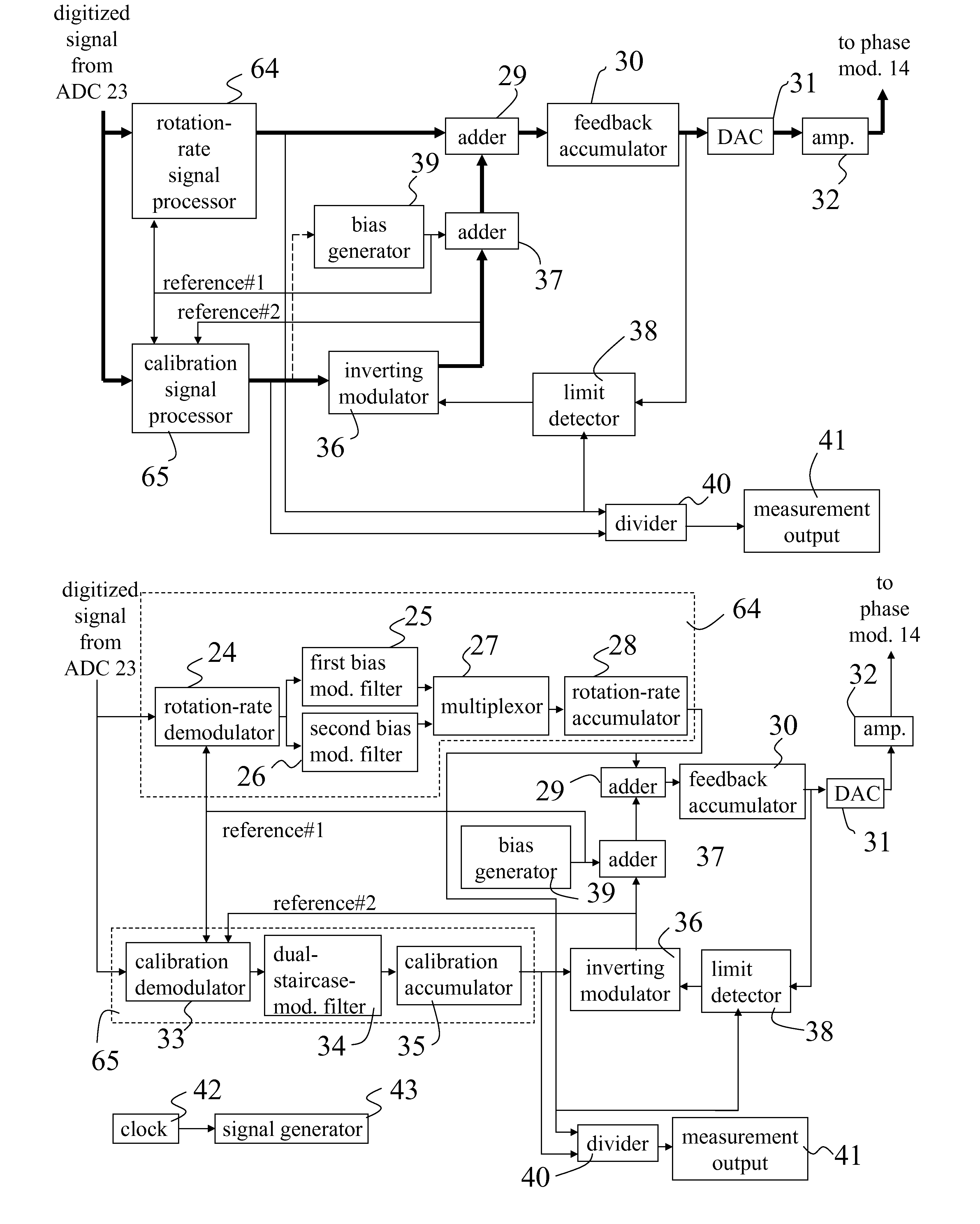
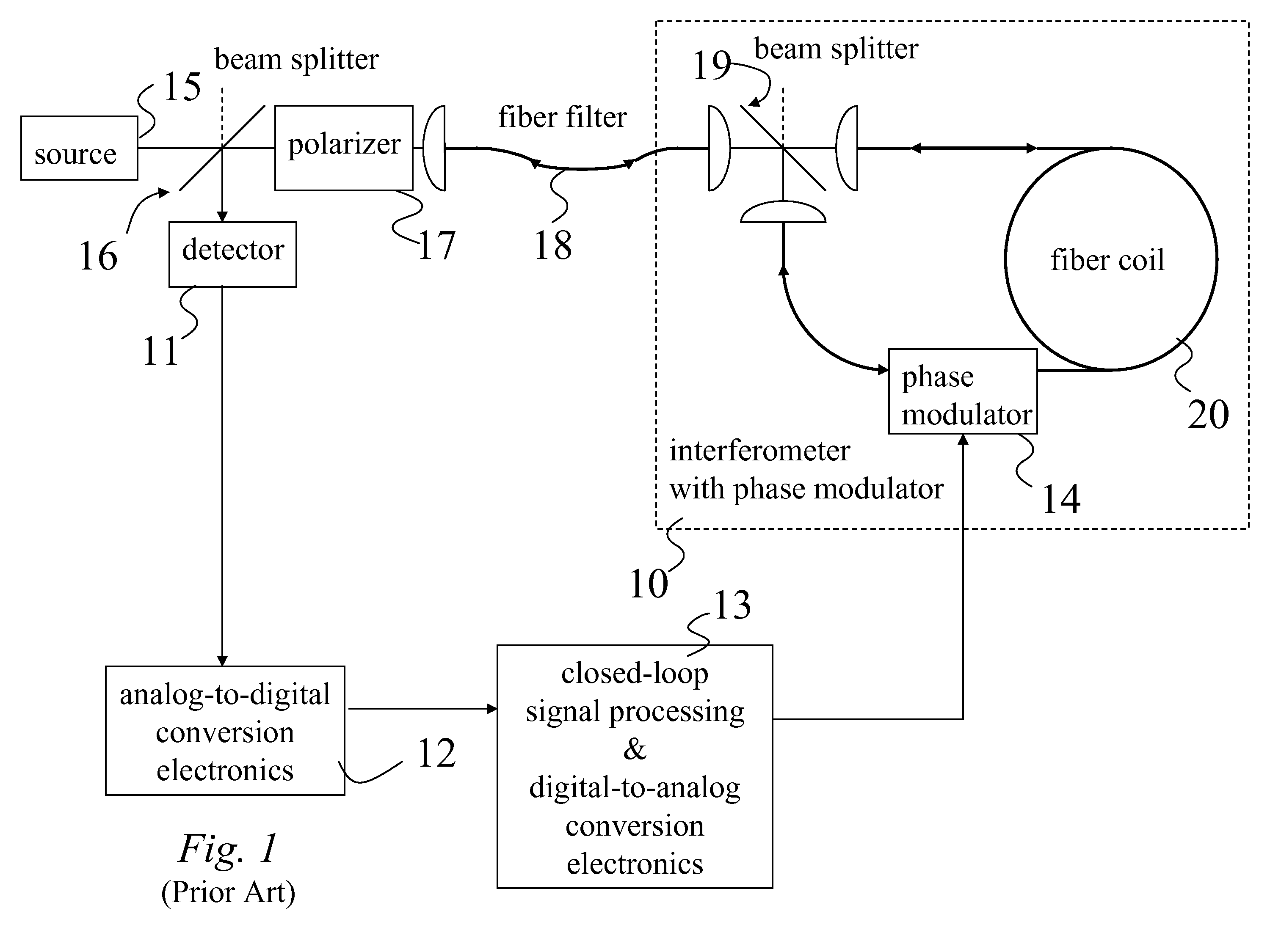
[0059]A general block diagram of the fiber optic gyroscope employed in accordance with the present invention, and also of the prior art, is depicted in FIG. 1 as aforedescribed in the prior art subsection “B. Basic Fiber Gyroscope Design”. The closed loop signal processing & digital-to-analog (DAC) conversion electronics 13 may take on a variety of forms as will be described with reference to the block diagrams of FIGS. 4 and 7 illustrating the prior art, and the block diagram of the present invention illustrated in FIG. 8. The differences between the present invention and the prior art are explained in part by comparing these block diagrams and by comparing the modulation waveforms of the invention shown in pictographs of FIGS. 9-12 to the prior-art waveforms shown in the pictographs of FIGS. 5 and 6 descriptive of the behavior of the present invention.

[0060]In the following exposition, phase modulation and phase difference modulation will first be discussed, follow...


PUM


Abstract

Disclosed is a method and apparatus for modulating the phase difference between a pair of optical waves that exit a Sagnac interferometer, and, more particularly, one that is commonly employed as a fiber gyro, and includes a detector responsive to phase difference between the pair of waves that exit the interferometer, and a phase modulator that forms part of two control loops that are instrumental in deriving an accurate measurement of rotation rate. As disclosed herein, phase modulation applied equally to the pair of waves as they counter-propagate through the phase modulator induces modulation of the phase-difference between the two waves as they exit the interferometer. This phase difference modulation includes (i) a bias phase-difference modulation component having a selected frequency, amplitude, and waveform, (ii) a rotation-rate feedback phase-difference component that is equal in magnitude to, and opposite in sign of, the Sagnac phase difference, so that the sum thereof is controlled to be substantially zero, and (iii) a calibration feedback phase-difference modulation component that is characterized by a predetermined phase difference magnitude having substantially alternating positive and negative sign values.

Description

FIELD OF THE INVENTION[0001]The present invention relates, in general, to gyroscopes and, more particularly, to closed-loop fiber optic gyroscopes and, even more particularly, closed-loop fiber optic gyroscopes using a Sagnac interferometer.BACKGROUND OF THE PRESENT INVENTIONA. Overview[0002]A Sagnac interferometer comprises a splitting plate or other splitting device that divides an incident light wave into two lightwaves. The two waves thus created enter opposite ends of a single optical path formed into a loop. The two waves counter-propagate, pass through each other, and return to the splitting device. There they recombine and are sent to a detector where they produce interference that depends upon phase difference between the recombined waves.[0003]Originally, mirrors defined the optical path of the Sagnac interferometers. It is now known that this optical path can be created using a single-mode optical fiber wound about an axis into a coil.[0004]It is also known that rotating ...

Claims


Application Information

Patent Timeline
Patent Type & Authority Patents(United States)
IPC IPC(8): G01C19/72
CPCG01C19/726
Inventor BERGH, RALPH A.
Owner BERGH RALPH A
Why Eureka
Try Eureka