Multi-channel mesh network

Inactive Publication Date: 2009-03-17
HITACHI ENERGY SWITZERLAND AG
View PDF48 Cites 39 Cited by
  • Summary
  • Abstract
  • Description
  • Claims
  • Application Information

AI Technical Summary

Benefits of technology

[0009]The invention includes an apparatus and method for a multiple channel

Problems solved by technology

However, mesh networks having a single transmission frequency can still suffer from transmission signal degradation.
Upstream traffic of an access node can suffer from congestion if a larg

Method used


Image

  • Multi-channel mesh network
  • Multi-channel mesh network
  • Multi-channel mesh network

Examples


Embodiment Construction

[0022]As shown in the drawings for purposes of illustration, the invention is embodied in a multiple channel mesh network that provides enhanced throughput and transmission reliability.

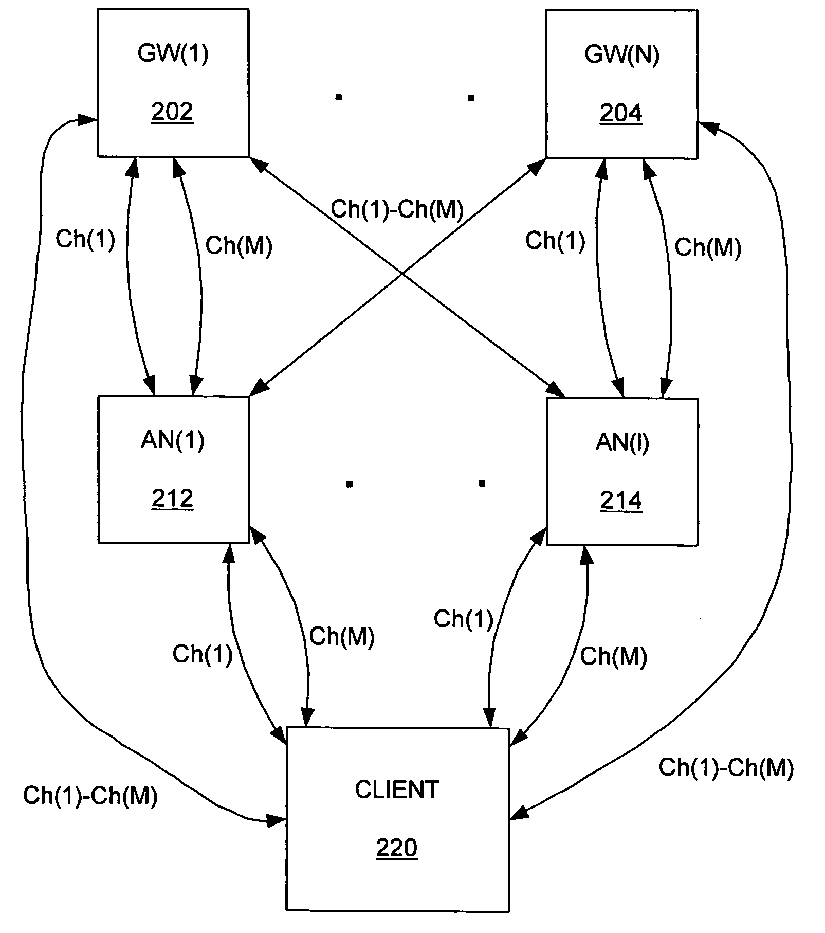
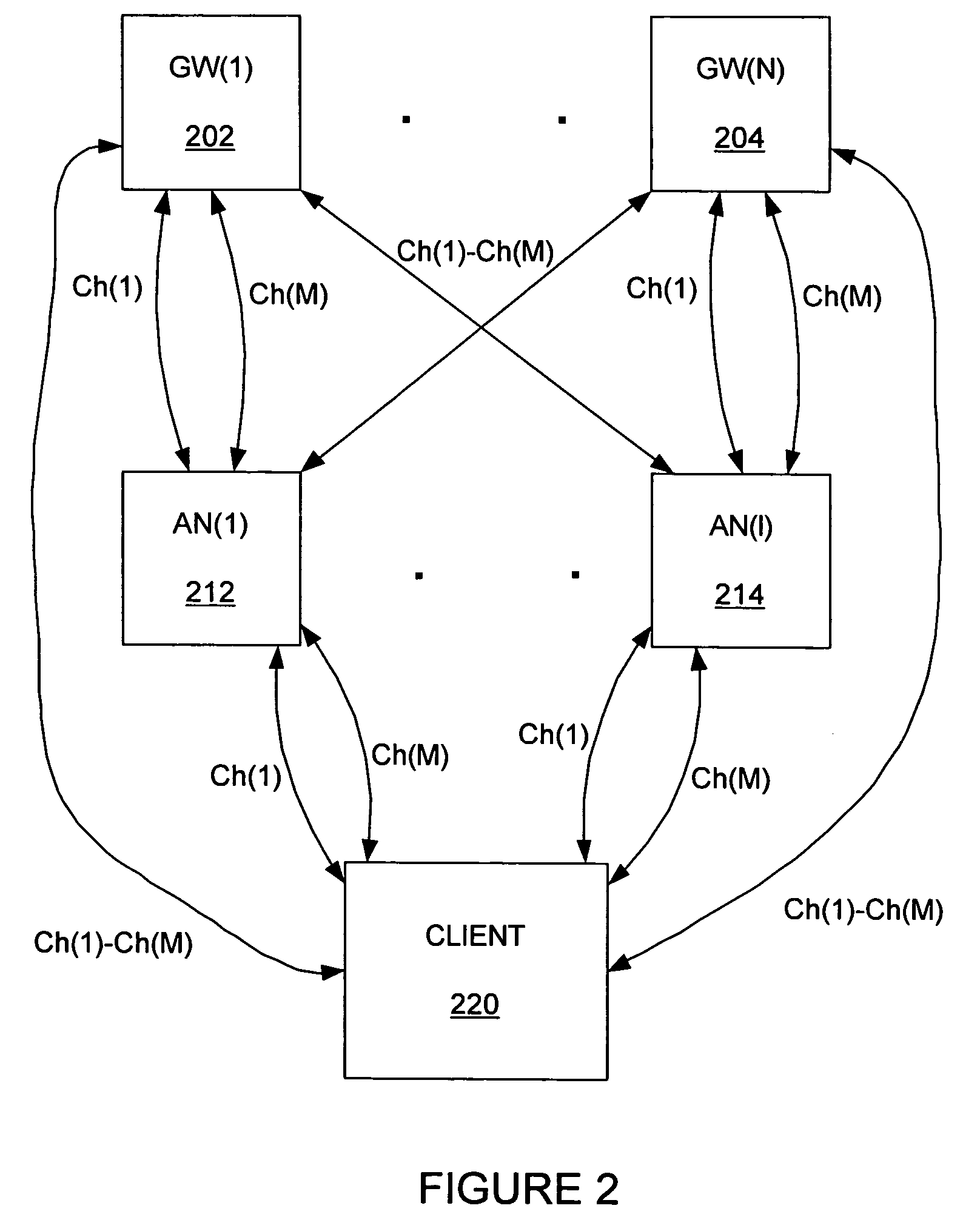
[0023]FIG. 2 shows a mesh network that includes multiple transmission channels. The mesh network includes gateways 202, 204, access nodes 212, 214 and a client 220. Generally, wireless transmission signals provide communication between the gateways 202, 204, the access nodes 212, 214 and client 220. As shown in FIG. 2, the transmission signals can travel through one or more of M available transmission channels Ch1-ChM.

[0024]A gateway is typically a wired device that provides a wireless access node access to a network. The gateway is a network entity that maintains an address-mapping table for each client. The address-mapping table generally includes a MAC-IP address mapping for the client devices. As will be described, one or more gateways can correspond with each access node, and each gateway can ser...


PUM


Abstract

A method of selecting at least one routing path between and access node and a gateway is provided. The method includes the access node receiving over a plurality of channels, indicators from at least one upstream access node, the indicators providing information of selected upstream paths between each of the upstream access nodes and upstream gateways. The access node determines an optimal set of routing paths between the access node and at least one upstream gateway, based upon the indicators, the optimal set of routing paths including a combination of paths over multiple channels.

Description

CROSS REFERENCE TO RELATED APPLICATIONS[0001]This application is a continuation-in-part (CIP) of U.S. patent application Ser. No. 10 / 693,721 filed on Oct. 25, 2003, titled “Method and Apparatus to Provide a Routing Protocol for Wireless Devices” which is a continuation of U.S. patent application Ser. No. 09 / 751,262 filed on Dec. 29, 2000, having the same title, and granted as U.S. Pat. No. 6,704,301.FIELD OF THE INVENTION[0002]The invention relates generally to communication networks. More particularly, the invention relates to a multi-channel mesh network.BACKGROUND OF THE INVENTION[0003]Wireless access devices are becoming more prevalent. Wireless access can be implemented in many different forms, including connecting a wireless access device (client) through a wireless mesh network that provides connection to a wired device. FIG. 1 shows a wireless mesh network that includes a client device 140. The client device 140 is wirelessly connected to an access node 130. The wireless acc...

Claims


Application Information

Patent Timeline
IPC IPC(8): H04H20/71H04L12/26H04L12/28H04L12/56H04L12/66H04W40/12H04W40/22H04W48/16
CPCH04L45/00H04L45/125H04L45/20H04L45/22H04W40/02H04W40/12H04W40/22H04W88/04H04W40/10H04W40/246H04W40/26H04W40/30H04W40/32H04W48/16
Inventor SRIKRISHNA, DEVABHAKTUNICHARI, AMALAVOYAL
Owner HITACHI ENERGY SWITZERLAND AG
Why Eureka
Try Eureka