
X-ray imaging of baggage and personnel using arrays of discrete sources and multiple collimated beams

a technology of x-ray imaging and discrete sources, applied in the direction of nuclear radiation detection, instruments, measurement devices, etc., can solve the problems of affecting the image quality of the image data, unable to meet the size constraints imposed by certain venues such as airports, and inadequate throughput of certain applications

Active Publication Date: 2009-03-17
AMERICAN SCI & ENG INC
View PDF48 Cites 148 Cited by
  • Summary
  • Abstract
  • Description
  • Claims
  • Application Information

AI Technical Summary

Benefits of technology

The present invention provides a method for imaging an object using a plurality of discrete X-ray sources that illuminate the object with a beam varying in spatial orientation. The X-rays are detected and a detector signal is generated, which is then used to construct an image of the object. The method may include moving the X-ray sources in a prescribed temporal pattern and / or characterizing them by an array axis. The invention also provides an inspection system with a plurality of linear arrays of discrete sources of penetrating radiation and a scatter detector for inspecting an object. The technical effects of the invention include improved image quality and more accurate inspection of objects using X-ray imaging techniques.

Problems solved by technology

While backscatter x-ray scanning of personnel is often considered the most effective method for detection of concealed contraband goods or potential threats, current implementations of this technology may provide inadequate throughput for certain applications, and, moreover, may fail to meet size constraints imposed by certain venues such as airports.
Because the x-ray beam of these sources is collimated into a fan beam shaped line of x-rays, the angle of incidence on the person being screened can cause distortion in the image data.
At steep angles this can result in x-ray incident shadows (from body parts such as shoulders) and thus, in turn, cause concealed contraband to be missed.
If several conventional x-ray sources are used to mitigate this effect, the equipment size becomes large and the equipment cost becomes unattractive.

Method used


Image

  • X-ray imaging of baggage and personnel using arrays of discrete sources and multiple collimated beams
  • X-ray imaging of baggage and personnel using arrays of discrete sources and multiple collimated beams
  • X-ray imaging of baggage and personnel using arrays of discrete sources and multiple collimated beams

Examples


Embodiment Construction

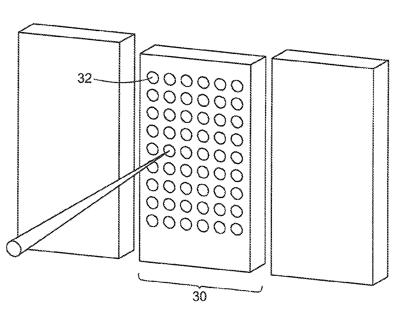
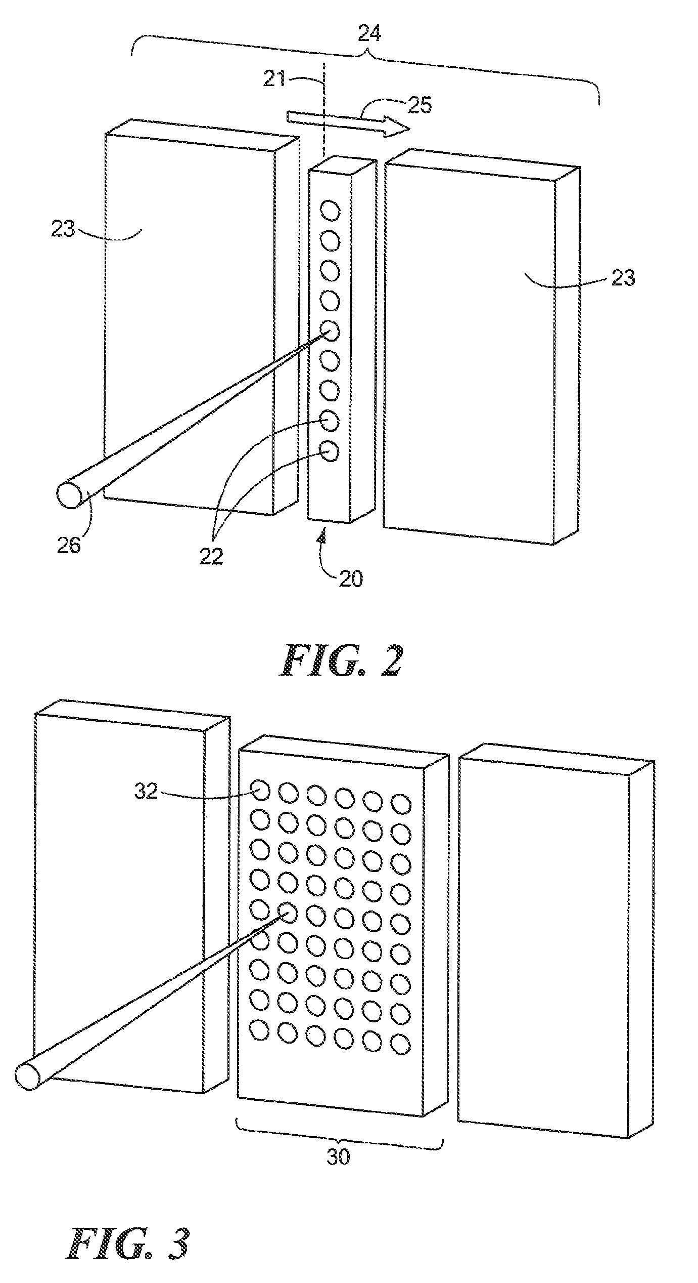
[0028]Cold cathode technology, such as that based on carbon nanotubes (CNTs), opens up the possibility of new modalities for imaging using X-rays, whether by transmission, backscatter, or forward scatter of the X-rays. Applied in the manner described below in accordance, with the present invention, discrete cold cathode sources may advantageously provide for electronically turning on the sources, and with low latency (on the nanosecond scale), in a sequential manner, thereby forming pencil beams, as often practiced in the X-ray imaging arts, or, alternatively, selecting a pattern of sources at a given time to form coded beams. The development of CNTs has allowed important technical challenges related to current stability and cathode life time to be overcome.

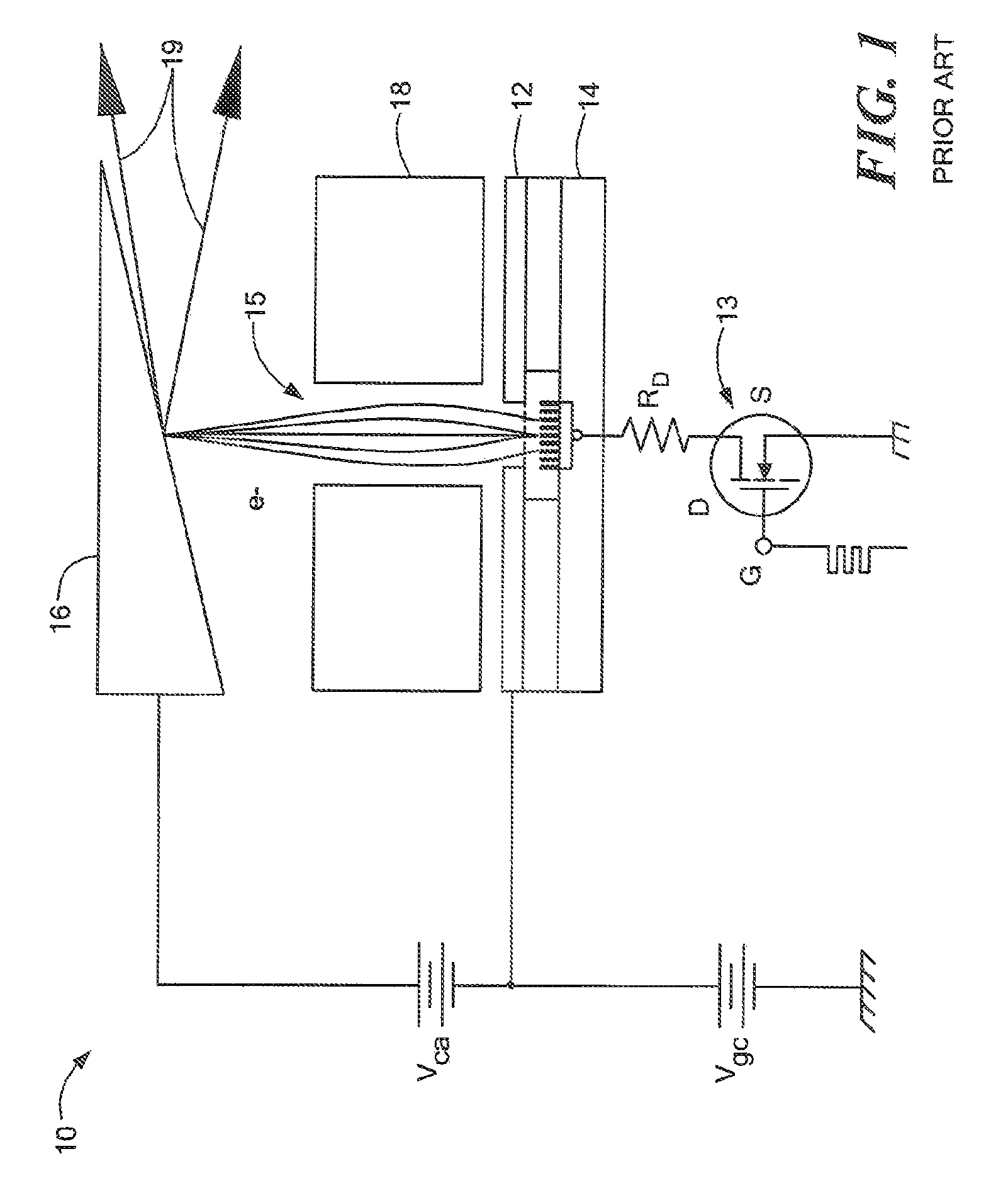
[0029]The general operation of a cold cathode X-ray source, designated generally, in FIG. 1, by numeral 10, is well understood in the art and is described with reference to FIG. 1. The cold cathode arrangement advantageously allo...


PUM

PropertyMeasurementUnit
distanceaaaaaaaaaa
distanceaaaaaaaaaa
timeaaaaaaaaaa

Abstract

A system and methods are provided for imaging an object, based on activating an array of discrete X-ray sources in a prescribed temporal pattern so as to illuminate the object with a beam varying in spatial orientation, and detecting X-rays of the beam after interaction with the object and generating a detector signal. An image of the object may then be constructed on the basis of the time variation of the detector signal. The discrete X-ray sources may be moved during the course of inspection, moreover, the prescribed temporal pattern may constitute a Hadamard code. The discrete sources may be carbon nanotube x-ray sources.

Description

[0001]The present application claims priority on the basis of U.S. Provisional Patent Application Ser. No. 60 / 794,295, entitled “X-ray Imaging using Arrays of Discrete to Sources,” filed on Apr. 21, 2006, incorporated herein by reference.TECHNICAL FIELD[0002]The present invention relates to methods and systems for inspecting objects, including personnel but not limited thereto, by means of penetrating radiation, and more particularly, to inspection of personnel using multiple x-ray sources that may be individually activated.BACKGROUND OF THE INVENTION[0003]Conventional X-ray sources typically use a thermionic emission mechanism to produce electrons that impinge on a metallic target from which x-rays are emitted through bremsstrahlung processes. Thermionic emission entails the emission of electrons by heated filaments. Thermal inertia limits the time resolution of thermionic systems to microseconds, while spatial resolution of the electron emitter is governed by the dimension of the ...

Claims


Application Information

Patent Timeline
Patent Type & Authority Patents(United States)
IPC IPC(8): G01N23/201
CPCG01N23/201G01N23/203G01V5/0025G01V5/222
Inventor DINCA, DAN-CRISTIANMASTRONARDI, RICHARDROTHSCHILD, PETER J.
Owner AMERICAN SCI & ENG INC
Learn More