
Apparatus for measuring temperature using luminescence thermometry

Inactive Publication Date: 2009-03-24
ROLLS ROYCE PLC
View PDF12 Cites 10 Cited by
  • Summary
  • Abstract
  • Description
  • Claims
  • Application Information

AI Technical Summary

Benefits of technology

[0010]The physical separation of photon emission and photon reception improves the efficiency of temperature detection, particularly at high temperatures where emission may become weak and may increase the high temperature range of temperature detection. It also enables the collection area for photons to be independently optimised to reduce the amount of noise from black body radiation which increases the detection efficiency at higher temperatures. This may also increase the high temperature range of temperature detection.

Problems solved by technology

However, the use of the same fibre for emission and collection creates fluorescence which adds noise.

Method used


Image

  • Apparatus for measuring temperature using luminescence thermometry
  • Apparatus for measuring temperature using luminescence thermometry

Examples


Embodiment Construction

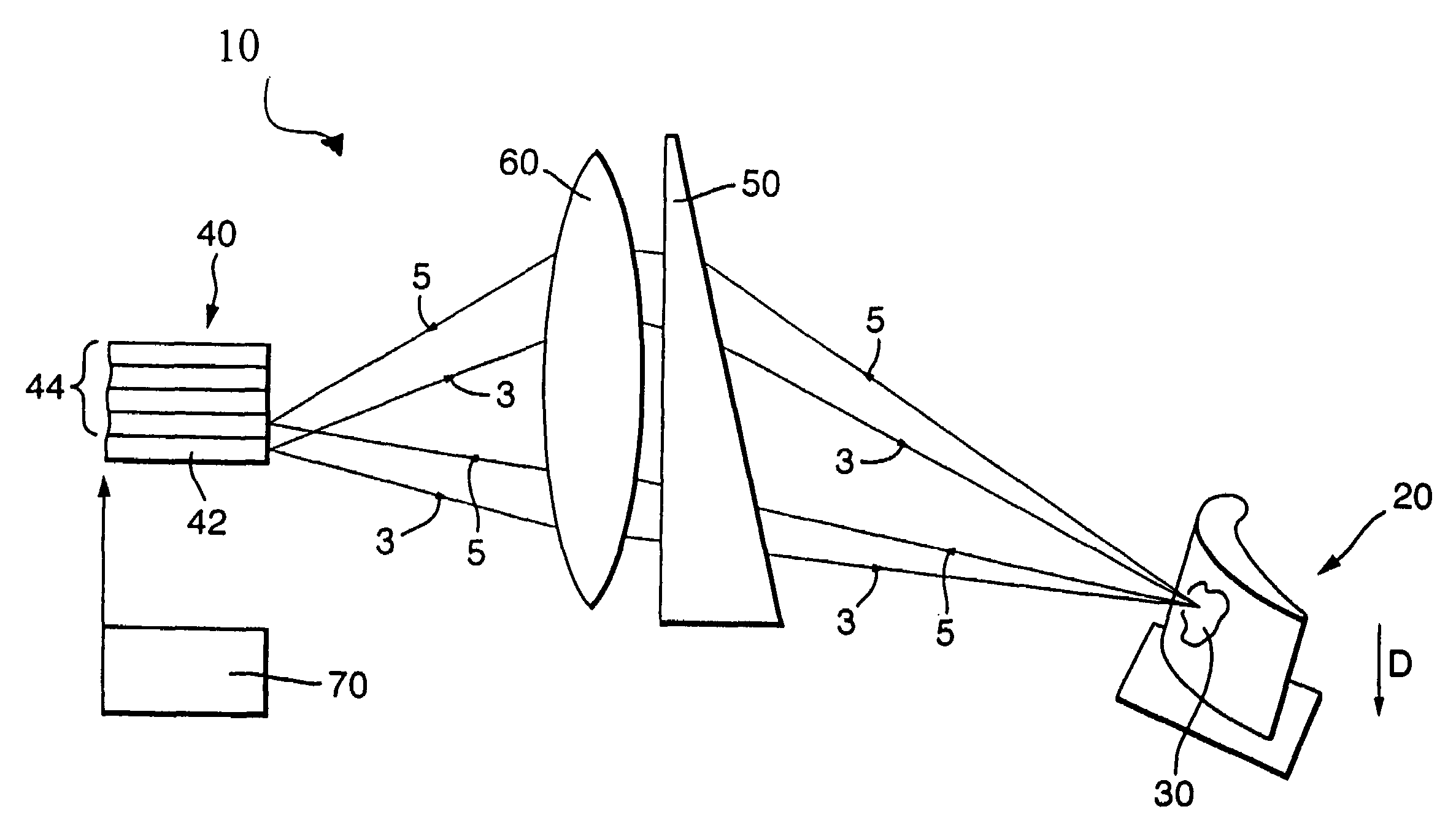
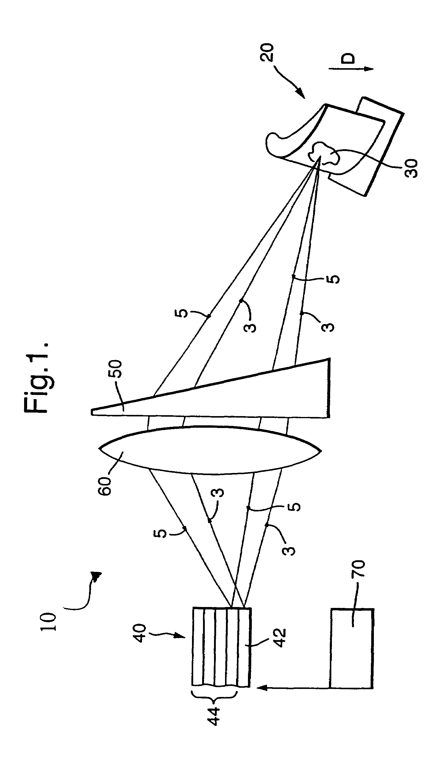
[0019]FIG. 1 illustrates an apparatus 10 for measuring the temperature of an object 20 using luminescence thermometry. The apparatus 10 comprises: the object 20 carrying photoluminescent material 30; a bundle of optical fibres 40 including a photon emitter fibre 42 and photon receiver fibres 44; an optically dispersive element 50; a lens system 60 and a detection and control mechanism 70.

[0020]A portion of the object 20 has been covered with photoluminescent material 30. When photons 3 of a first frequency (e.g. ultra violet) are incident on the photoluminescent material, it emits photons 5 of at least a second frequency (e.g. visible) in response to the incidence of the photons 3 of the first frequency.

[0021]A pulse or series of pulses of photons 3 of the first frequency are provided by the photon emitter optical fibre 42. The photons pass through the lens system 60 and dispersive element 50 and are incident on the photoluminescent material 30. The photon emitter fibre 42 is used f...


PUM


Abstract

An apparatus (10) for measuring temperature using luminescence thermometry, comprising: a photon emitter (42) for providing photons (3) of at least a first frequency; photoluminescent material (30) that produces photons (5) of at least a second frequency in response to the incidence of photons (3) of the first frequency; one or more photon receivers (44); and an optically dispersive element (50) for directing photons (5) of at least a second frequency produced by the photoluminescent material (30) into the photon receiver(s).

Description

[0001]This is a continuation of International Application Number PCT / GB2004 / 003731 filed Sept. 3, 2004, designating the United States.FIELD OF THE INVENTION[0002]Embodiments of the invention relate to an apparatus for measuring, using luminescence, and in particular for measuring temperature using luminescence thermometry.BACKGROUND OF THE INVENTION[0003]Luminescence thermometry is presently used to determine the temperature of an object without having to make physical contact with the object.[0004]A photoluminescent material commonly known as a thermographic phosphor is applied to the object whose temperature is to be measured. The photo luminescent material is stimulated with pulsed UV light. The photoluminescent material emits, in response, a pulse of light generally at a lower frequency (e.g. visible light). This pulse decays exponentially with time. The exponent is related to the temperature of the luminescent material and hence the temperature of the object. The pulses emitted...

Claims


Application Information

Patent Timeline
IPC IPC(8): G01K11/00G01K11/20
CPCG01K11/20
Inventor BIRD, COLIN
Owner ROLLS ROYCE PLC
Learn More