X-ray radiator with a photocathode irradiated with a deflected laser beam

a technology of x-ray radiator and laser beam, which is applied in the direction of x-ray tube cathode assembly x-ray tube cooling, etc., can solve the problems of focusing electron beam, generating soft x-ray radiation, and the use of such an x-ray tube is only in a limited manner, and achieves the effect of flexible and suitable for industry

Inactive Publication Date: 2009-03-24
SIEMENS AG
View PDF11 Cites 9 Cited by
  • Summary
  • Abstract
  • Description
  • Claims
  • Application Information

AI Technical Summary

Benefits of technology

[0013]An object of the present invention is to provide injection of a laser beam onto a cathode in a sealed x-ray tube in a manner that is particularly flexible and suitable for industry.
[0015]This x-ray radiator allows a beam direction to be set particularly simply and flexibly. A greater distance between the site of the injection and the site of the generation of the electrons additionally can be produced, which can significantly reduce contamination of windows through which the beam must pass. Moreover, the manner of the injection is also suitable for realization in “non-mechanical CT” and can be realized with a high degree of effectiveness. Particularly compact designs are also possible.
[0017]The above x-ray radiator is not limited in type and, as noted above, be used in CT systems of the type known as “non-mechanical CTs”. However, it is advantageous when the vacuum housing can be rotated on an axis and the x-ray radiator has a drive for rotation of the vacuum housing around its axis. For a compact design and a reliable operation, it is then advantageous for the laser beam to be deflected off the rotation axis by the deflection arrangement from a beam direction that is essentially parallel to the rotation axis (in particular on the rotation axis) toward the cathode.
[0018]For a compact design it is particularly advantageous to provide an optically transparent window for passage of the laser beam into the vacuum housing, at the vacuum housing in the region of the rotation axis of the vacuum housing or on the anode side outside of the periphery of the anode. It can be advantageous for the laser beam to be injected into the vacuum housing on the anode side in the region of the rotation axis (thus generally proceeding through the anode). The deflection arrangement can the be provided in the vacuum region, or can already deflect the beam in the region of the anode before the vacuum.
[0021]For a simple beam direction and production it is advantageous for the deflection arrangement to be a reflection element that is arranged on the electrode situated opposite an optically transparent window, thus (for example) on the anode when the laser beam is injected on the cathode side, and vice versa.
[0023]It is also possible to mount the surface of the cathode on a support layer (substrate), so the laser beam is directed through the support layer of the cathode onto the surface of the cathode, for example without having to enter into the vacuum housing. For increased injection efficiency and to protect against clouding of the window, it is advantageous to form the cathode as a circular ring, in particular with large diameter.

Problems solved by technology

This creates problems in the focusing of the electron beam.
Among other things, a problem occurs in the generation of soft x-ray radiation given which a comparably low voltage is applied between cathode and anode.
The use of such an x-ray tube is possible only in a limited manner for specific applications (such as, for example, mammography).
The practical feasibility of this concept, however, appears to be questionable due to the quantum efficiency of available photo-cathodes and the light power that is required.
Given use of high light power, the cooling of the photo-cathode requires a considerable expenditure due to its rather low heat resistance.
In view of the vacuum conditions that exist in x-ray tubes, the surface of the photo-cathode is additionally subjected to oxidation processes, which limits the durability of such an x-ray tube.
The longer electron flight path with repeated deflection of the electron beam between the dynodes, however, requires a high expenditure for focusing the beam.
The surface of the cathode should be capable of being heated and cooled quickly in the disclosed embodiment of the cathode with a substrate layer made of a material with high heat conductivity, but this appears to be problematic with regard to the light power that is required.

Method used


Image

  • X-ray radiator with a photocathode irradiated with a deflected laser beam
  • X-ray radiator with a photocathode irradiated with a deflected laser beam
  • X-ray radiator with a photocathode irradiated with a deflected laser beam

Examples


Embodiment Construction

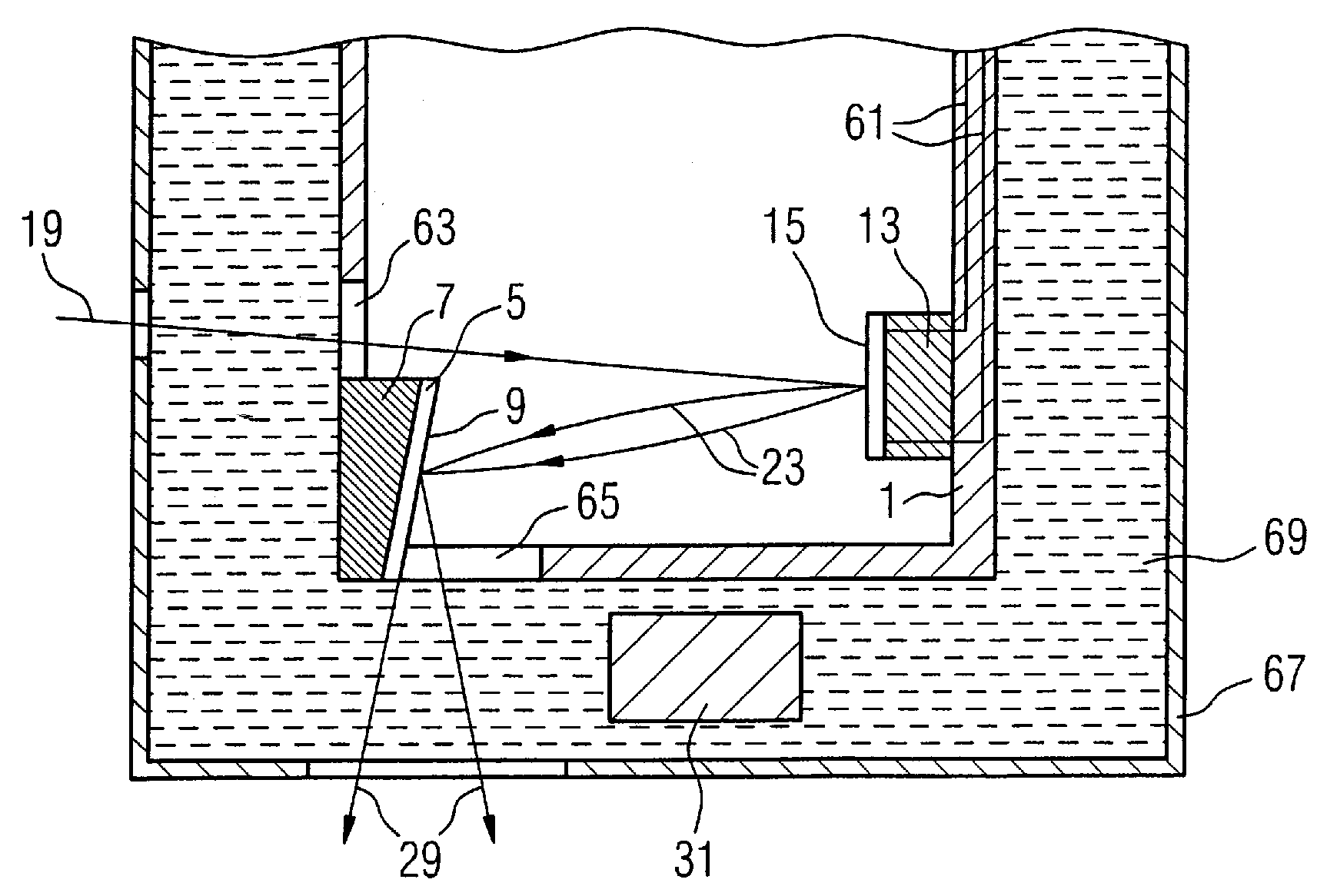
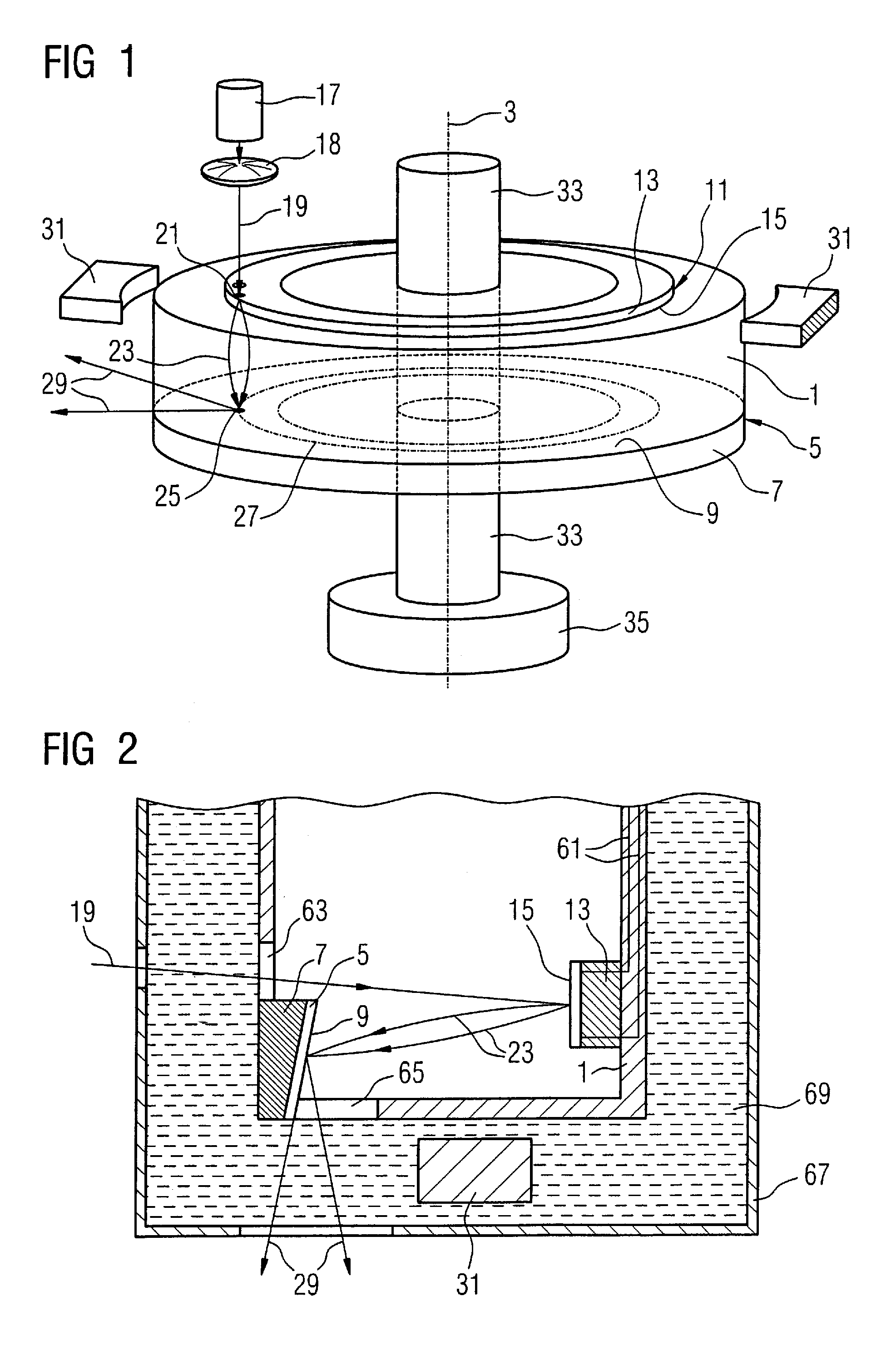
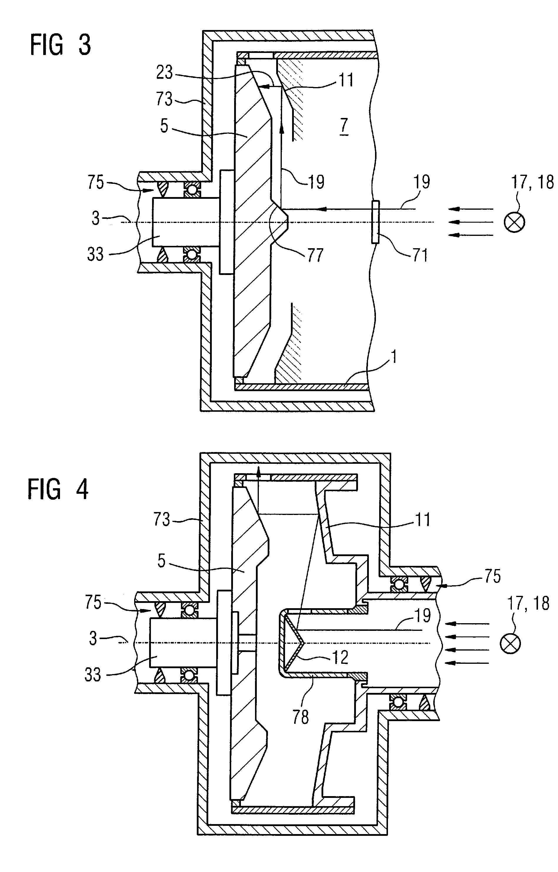
[0028]A three-dimensional representation of a vacuum housing 1 is shown in FIG. 1. The vacuum housing 1 is fashioned as a cylinder (having a cylinder jacket formed of an insulating material) and the cylinder is mounted in a rotationally symmetrical manner on an axis 3. An anode 5 forms a base of the cylinder. The anode 5 has a support layer 7 and an annularly-fashioned surface 9 from which x-rays 29 are emitted. An annularly-fashioned cathode 11 is located in the opposite base of the vacuum housing 1 (cylinder). The cathode 11 has a support layer 13 that is part of the exterior of the vacuum housing 1 and a surface 15 that facing the interior of the vacuum housing 1.

[0029]The anode 5 and cathode 11 shown in FIG. 1 are fashioned axially symmetrically, such that the electron beam or the laser beam always strikes the surface of the anode 5, or the cathode 11 during the rotation. However, it can also be advantageous to fashion the anode 5 and the cathode 11 (in particular their support ...


PUM


Abstract

An x-ray radiator has an anode that emits x-rays, a cathode that thermionically emits electrons upon irradiation thereof by a laser beam, a voltage source for application of a high voltage between the anode and the cathode for acceleration of the emitted electrons toward the anode to form an electron beam, a vacuum housing, an insulator that is part of the vacuum housing and that separates the cathode from the anode, an arrangement for cooling components of the x-ray radiator, a deflection and arrangement that deflects the laser beam from a stationary source, that is arranged outside of the vacuum housing, to a spatially stationary laser focal spot on the cathode.

Description

BACKGROUND OF THE INVENTION[0001]1. Field of the Invention[0002]The present invention concerns an x-ray radiator with a cathode and an anode, of the type wherein the cathode has a surface that emits electrons upon laser irradiation of the surface.[0003]2. Description of the Prior Art[0004]High-capacity x-ray radiators typically have an anode that is mounted to rotate in order to ensure a high thermal loading capability of the anode during generation of x-rays with high radiation power.[0005]DE 87 13 042 U1 describes an x-ray tube with an evacuated housing (the housing is evacuated in order to be mounted such that it can be rotated around a rotation axis) in which a cathode and an anode are arranged. The cathode and the anode are connected in a fixed manner with the housing. The x-ray tube has drive means for rotation of the housing around the rotation axis. A deflection system that is stationary relative to the housing deflects an electron beam proceeding from the cathode to the ano...

Claims


Application Information

Patent Timeline
Patent Type & Authority Patents(United States)
IPC IPC(8): H01J35/06H01J35/10
CPCH01J35/065H01J35/101H01J35/16H01J2235/062H01J2235/066H01J2235/10H01J2235/1216H01J2235/162
Inventor DITTRICH, RONALDFREUDENBERGER, JOERGFRITZLER, SVENFUCHS, MANFREDMATTERN, DETLEFROEHRER, PETERSCHARDT, PETER
Owner SIEMENS AG
Why Eureka
Try Eureka