
Implantable pressure transducer system optimized for anchoring and positioning

a technology of pressure transducer and positioning device, which is applied in the field of optimizing the performance and minimizing complications of implanted sensors, can solve the problems of chf-related mortality worse than many common cancers, shortening of breath, acidosis, etc., and reducing the risk of thrombosis. , the effect of facilitating optimal healing and subsequent stability

Inactive Publication Date: 2009-03-24
PACESETTER INC
View PDF57 Cites 173 Cited by
  • Summary
  • Abstract
  • Description
  • Claims
  • Application Information

AI Technical Summary

Benefits of technology

The present invention provides several embodiments of an implantable pressure sensor that can be chronically implanted in the body and remain stable over a long period of time. These sensors are designed to be stable despite the biological reactions that occur in the body and can reduce the risk of thrombus formation and tissue overgrowth. The sensors can also be enclosed in protective packaging to prevent thrombus formation and minimize viscoelastic drift. The invention also provides several methods for deploying, anchoring, and retrieving the sensors, as well as a sensor design that reduces the impact of output artifacts and temperature compensation. Overall, the invention improves the stability and accuracy of implantable pressure sensors for use in the cardiovascular system.

Problems solved by technology

Although survival rates have improved, the mortality associated with CHF remains worse than many common cancers.
This complication of CHF is called pulmonary edema, which can cause shortness of breath, hypoxemia, acidosis, respiratory arrest, and death.
However, pressure sensors that are currently described in the art are not suitable for chronic implantation in the body for several reasons.
For example, some pressure transducers are not hermetically sealed, or otherwise properly protected, and thus susceptible to degradation by bodily fluids.
Other transducers are constructed such that their specific geometries or components cause thrombus formation, a potentially life threatening condition.
Several transducers are constructed in a manner that result in significant “drift” of the pressure sensor, either due to tissue overgrowth or some other mechanism, thus resulting in inaccurate pressure measurements, which in many cases cannot be properly or easily recalibrated.

Method used


Image

  • Implantable pressure transducer system optimized for anchoring and positioning
  • Implantable pressure transducer system optimized for anchoring and positioning
  • Implantable pressure transducer system optimized for anchoring and positioning

Examples


example 1

In Vivo Studies

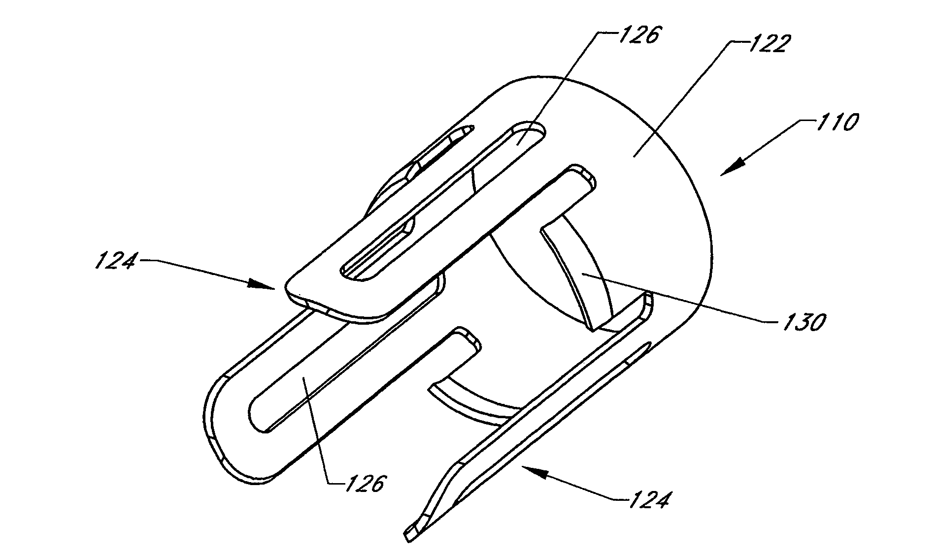
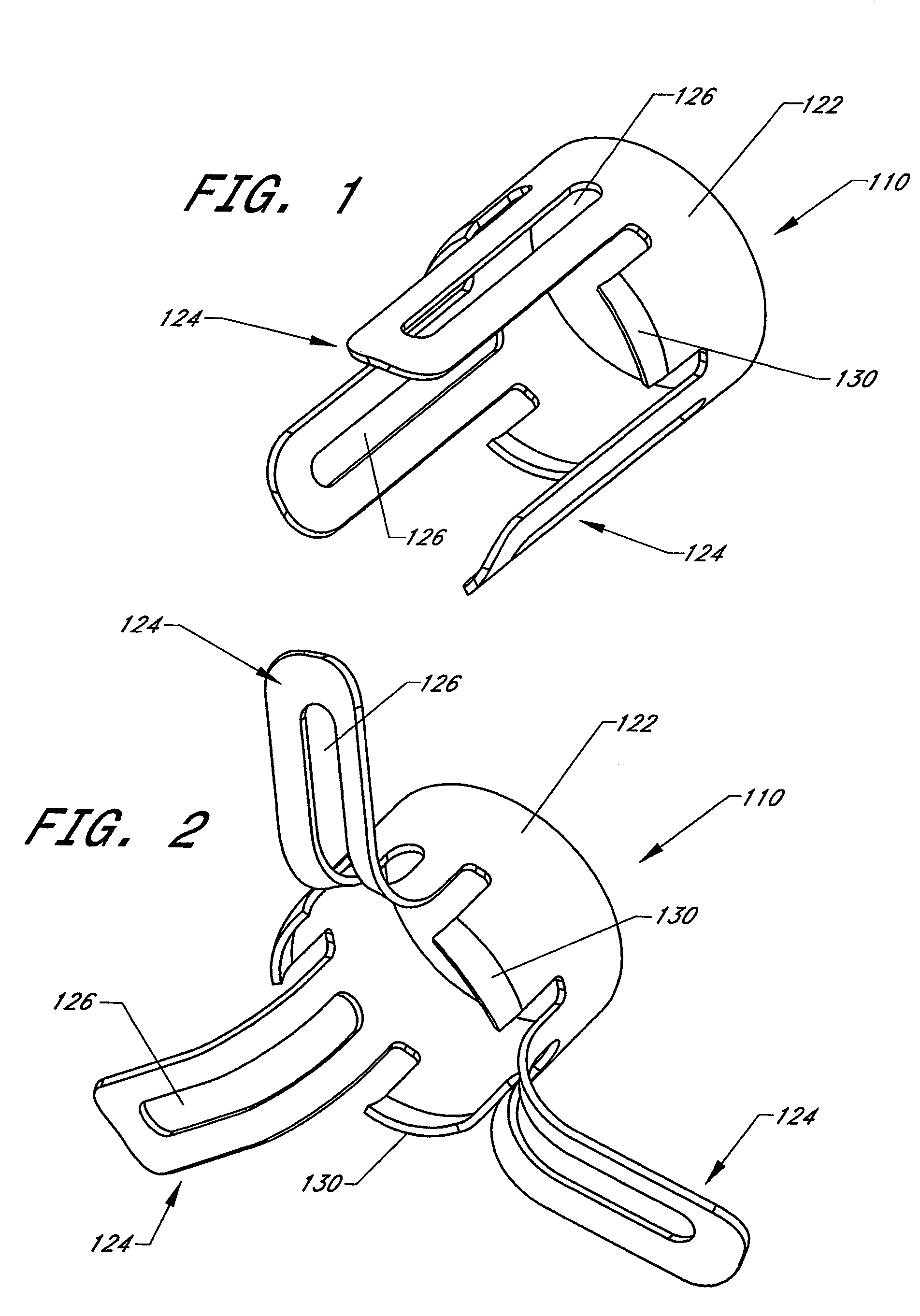
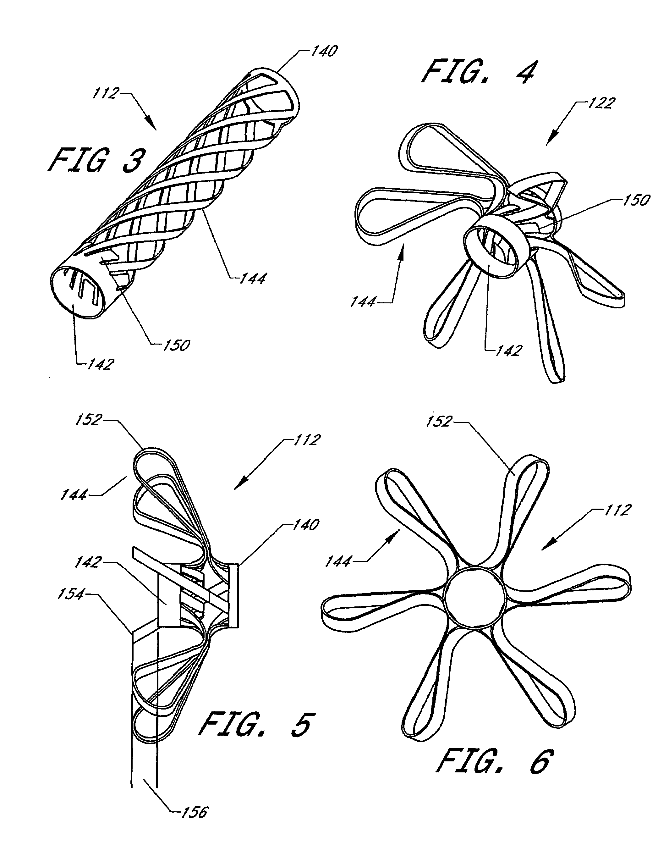
[0225]Several of the discoveries in this patent application results from the inventor's first hand experience percutaneously implanting transmural pressure transducer and anchor systems with catheter delivery systems similar to those depicted in FIGS. 1 through 21, in the left atrium of 3 anesthetized pigs. In these experiments, a transseptal catheterization was performed from the right internal jugular vein placing the distal tip of an 11 French×25 cm long, peel-away, hemostatic valve, side-arm delivery catheter in the left atrium under fluoroscopic guidance (Pressure Products). The pressure transducer systems were delivered to the desired location traversing the septum each time. Pigs were observed with transducer system in situ for 0 days, 3 weeks, and 18 weeks and periodic ambulatory pressure readings were obtained using a radiofrequency telemetry system coupled to a palm type computer. The pigs survived for 3 and 18 weeks were returned to the catheterization labo...


PUM


Abstract

This invention relates generally to systems and methods for optimizing the performance and minimizing complications related to implanted sensors, such as pressure sensors, for the purposes of detecting, diagnosing and treating cardiovascular disease in a medical patient. Systems and methods for anchoring implanted sensors to various body structures is also provided.

Description

CROSS-REFERENCE TO RELATED APPLICATIONS[0001]The present application is a continuation of co-pending U.S. application Ser. No. 11 / 111,691 filed Apr. 21, 2005, which 1) claims priority under 35 U.S.C. §119(e) to U.S. Provisional Application No. 60 / 564,315 filed Apr. 22, 2004, and 2) is also a continuation-in-part of U.S. application Ser. No. 10 / 672,443 filed Sep. 26, 2003, now U.S. Pat. No. 7,149,587 which claims priority under 35 U.S.C. §119(e) to U.S. Provisional Application No. 60 / 413,758 filed Sep. 26, 2002, the disclosures of which are incorporated by reference herein in their entirety.BACKGROUND OF THE INVENTION[0002]1. Field of the Invention[0003]This invention relates generally to systems and methods for optimizing the performance and minimizing complications related to implanted sensors, such as pressure sensors, for the purposes of detecting, diagnosing and treating cardiovascular disease in a medical patient.[0004]2. Description of the Related Art[0005]There are approximat...

Claims


Application Information

Patent Timeline
Patent Type & Authority Patents(United States)
IPC IPC(8): A61N1/00A61B5/00A61B5/02A61B5/0215A61N1/18
CPCA61B5/0215A61M2025/0233A61M25/04A61N1/3629A61B5/6869A61B5/6882A61B8/12A61B17/3468A61M25/0108A61M31/002A61N2001/0578
Inventor EIGLER, NEAL L.MANN, BRIAN M.WHITING, JAMES S.HAFELFINGER, WERNER
Owner PACESETTER INC
Learn More