Semi-solid forming of metal-matrix nanocomposites

Active Publication Date: 2009-03-31
WISCONSIN ALUMNI RES FOUND
View PDF49 Cites 124 Cited by
  • Summary
  • Abstract
  • Description
  • Claims
  • Application Information

AI Technical Summary

Benefits of technology

[0011]A metal matrix nanocomposite, that is, a composite wherein small particles (having at least one dimension on the order of 100 nm or less) are dispersed throughout a metal matrix, can be formed by heating a metal above its liquidus temperature, thereby placing the metal in its liquid state. Nanoparticles may then be added to the liquid metal, preferably in amounts of 0.25%-5.0% of the weight of the overall mixture, and most preferably in amounts of 0.25%-2.0% of the weight of the mixture. The metal/nanoparticle mixture can then be agitated by subjecting the mixture to high-frequency (preferably >5 khz) vibration. Most preferably, ultrasonic vibration (>20 khz) is used, and is applied by at least partially inserting a vibrating probe/member into the mixture (or possibly multiple probes, e.g., where the volume of the mixture is large). Such vibration has been found effective to at least substantially uniformly disperse the nanoparticles throughout the mixture, usefully reducing or eliminating problems with clumping of the nanoparticles.
[0012]The mixture can then be cooled, and the vibrating member can be removed from the mixture. Preferably, at the latest, the vibrating member is removed when the metal is at or near its liquidus temperature (e.g., within about 50 C of the liquidus). Removal of the vibrating member can also occur after the liquidus is reached, but this is preferably avoided since it can promote solidification and build-up of the mixture on the vibrating member. It has been found that when the mixture is then cooled below the liquidus temperature of the metal (but above the metal's solidus temperature), it has an at least substantially globular microstructure which benef

Problems solved by technology

This result is surprising since ordinarily the temperature gradients arising from quenching promote a dendritic (non-globular) microstructure, thereby causing casting difficulties and/or nonuniformity in the strength and other properties of the ca

Method used


Image

  • Semi-solid forming of metal-matrix nanocomposites
  • Semi-solid forming of metal-matrix nanocomposites

Examples


Embodiment Construction

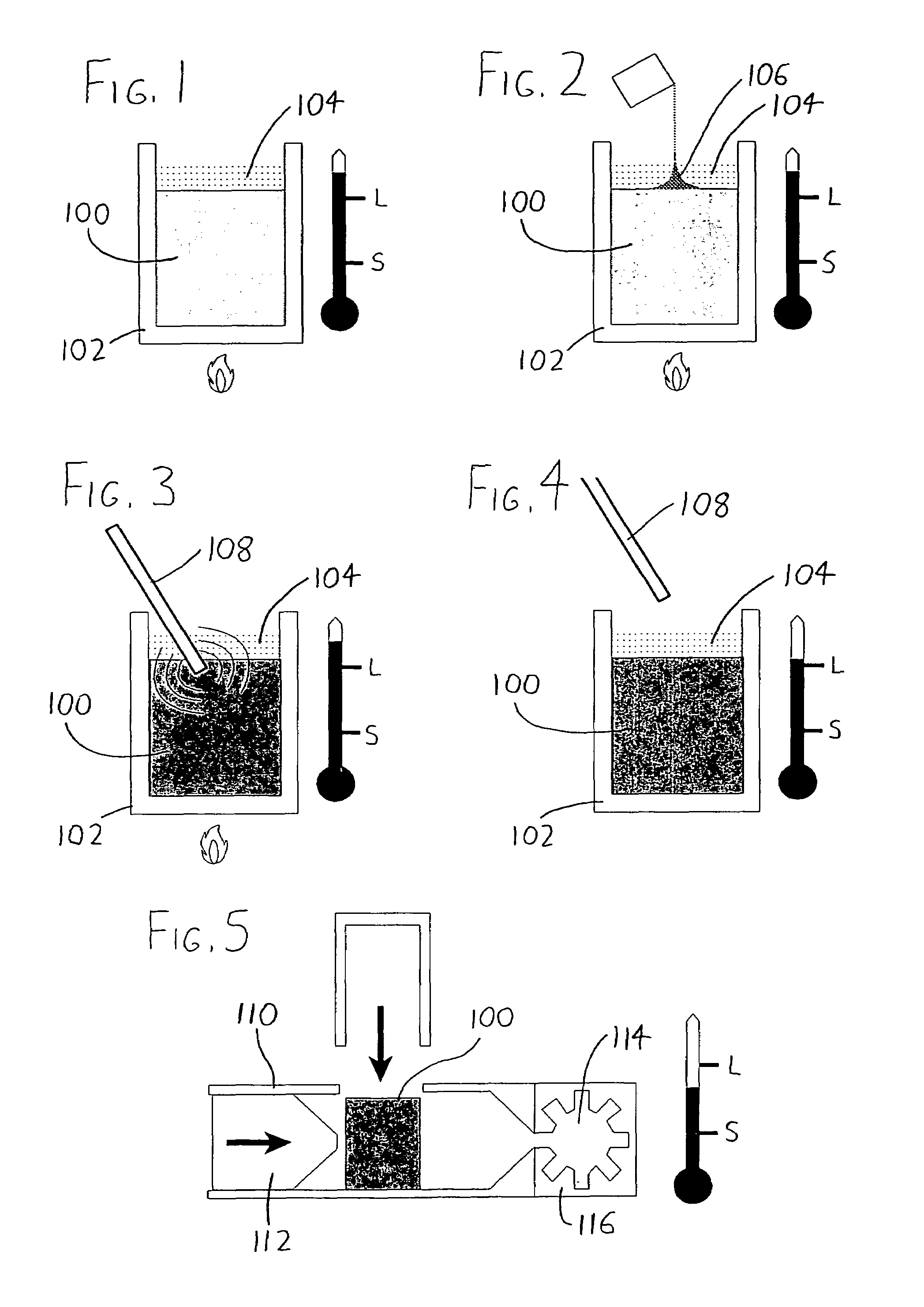
[0021]To expand on the discussion above, following is a more detailed explanation of an exemplary method for forming a metal matrix nanocomposite, with reference being made to the accompanying drawings.

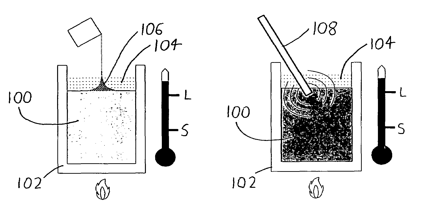
[0022]First, referring to FIG. 1, a metal 100 is brought to a temperature above its liquidus (preferably at least 50 C above). This can be done in any conventional manner, e.g., in a graphite crucible 102 using an electric resistance furnace. If desired, a cover gas 104 may be used to reduce oxidation of the molten metal 100.

[0023]As depicted in FIG. 2, nanoparticles 106 may then be added to the molten metal 100, preferably by simply applying them atop the surface of the metal 100. To promote faster mixing of the metal 100 and nanoparticles 106 during subsequent steps (discussed below), it may be useful to interrupt / pull back any oxide layer situated atop the molten metal 100 so that dispersion of the nanoparticles 106 is not hindered by the oxide layer. The nanoparticles 106 may addi...


PUM

PropertyMeasurementUnit
Frequencyaaaaaaaaaa
Frequencyaaaaaaaaaa
Weightaaaaaaaaaa

Abstract

A metal matrix nanocomposite is formed by heating a metal above its liquidus temperature, adding nanoparticles, and then agitating the mixture with high-frequency (and preferably ultrasonic) vibration. The mixture can then be cooled below the liquidus of the metal to a semisolid state, and placed in a mold to form it into some desired shape. The formed mixture can then be quenched or otherwise allowed to cool to provide an article in finished (or nearly so) form.

Description

STATEMENT REGARDING FEDERALLY SPONSORED RESEARCH[0001]This invention was made with United States government support awarded by the following agencies:[0002]National Science Foundation (NSF) Grant No. 0323509The United States government has certain rights in this invention.FIELD OF THE INVENTION[0003]This document concerns an invention relating generally to metal forming processes, and more specifically to methods for performing semisolid casting.BACKGROUND OF THE INVENTION[0004]High-pressure die casting (HPDC) is a process where metal (this term being used to refer to both metals and alloys) above its liquidus temperature, i.e., fully liquid metal, is injected into a cavity in a mold at high speed and pressure. HPDC is one of the most economical processes for mass production of cast metal items because of the short time needed for the casting cycle, the ability to make multiple items in a single casting, and the fact that the items leaving the mold may be in final form (or nearly so...

Claims


Application Information

Patent Timeline
IPC IPC(8): B22D19/14B22D17/00B22D27/04B22D27/08
CPCB22D17/007B22D27/08B82Y30/00C22C1/005C22C32/00Y10S164/90C22C1/12
Inventor TURNG, LIH-SHENGDECICCO, MICHAEL P.LI, XIAOCHUN
Owner WISCONSIN ALUMNI RES FOUND
Why Eureka
Try Eureka