Mixing element and static fluid mixer using same

a technology of mixing element and static fluid, which is applied in the direction of machines/engines, combustion air/fuel air treatment, and separation processes, etc., can solve the problems of high production cost, difficult to obtain the evenness of quality and homogeneity of reaction, and difficult to produce homogeneous mixed fluid, etc., to achieve low production cost, facilitate production, and high mixture efficiency

Active Publication Date: 2009-03-31
ANEMOS CO LTD
View PDF26 Cites 45 Cited by
  • Summary
  • Abstract
  • Description
  • Claims
  • Application Information

AI Technical Summary

Benefits of technology

[0033]A mixing element of the present invention for solving the above-mentioned problems is a mixing element includes: a cylindrical passage tube through which fluid flows; spiral first blades of rightward rotation (in the clockwise direction) or leftward rotation (in the counterclockwise direction) provided in the cylindrical passage tube; a first inner cylindrical tube disposed in the axial center portion of the first blades; spiral second blades of rightward rotation or leftward rotation provided in the first inner cylindrical tube; and a second inner cylindrical tube disposed in the axial center portion of the second blades. According to the present invention, a mixing element is provided, in which high mixture efficiency is obtained, production thereof is facilitated, and production cost is low. Further, a mixing element with low pressure loss and high mixture efficiency capable of being applied to a gas-liquid contact apparatus of a large diameter (1 m or more) of the distillation column method, stripping column method and absorption column method, and a static fluid mixer using the mixing element are provided.
[0034]According to a mixing element of the present invention, with improvement in packing density (m2 / m3), mixture and agitation efficiency will be improved, and so gas-liquid contact time will be reduced. Further, since the production is facilitated, production costs will be reduced as well. Further, the production of a distillation column or absorption column having a large diameter will be simplified. And again, high performance obtained by replacing packing used in a distillation column or absorption column in related art which already exists, and reduction in production costs due to energy saving are achieved. It should be noted that a packing density mentioned here (used later as well) shows the whole surface area (m2) of blades per unit volume (m3) of a mixing element. Specifically, it shows the whole surface area (m2) of first and second blades per unit volume (m3) in a passage tube.

Problems solved by technology

Also, regarding a plurality of agitation wings which are not spiral in form but are simply twisted, that are placed inside a short tube, since those agitation wings are not disposed evenly at regular intervals, fluid becomes channeling, which makes it difficult to produce a homogeneous mixed fluid, hence it is difficult to obtain the evenness of quality and the homogeneity of reaction.
Thus, production costs become high.
Further, in twisting agitation wings by means of a forging method, which is an inexpensive production method, cracks may occur in a metal plate material, so that it is difficult to produce agitation wings, and it may be impossible to produce a large diameter (1 m or more in diameter) in particular, because of the occurrence of cracks caused by a metal plate material expanding and contracting.
For that reason, there is a disadvantage that the effectiveness of mixture and agitation diminishes, because packing density lowers, and fluid flows directly in an opening, that is, a short circuit occurs.
Further, in order to compensate for the decrease in the effectiveness of mixture and agitation, it is necessary to provide a large number of mixing elements in the longitudinal axial center direction, so that equipment costs become high, and pressure loss becomes high as well.
Furthermore, if a mixing element of a large diameter (internal diameter of 1 m or more) with a rotation angle of 180°, for example, is produced by means of a forging method, production may become impossible because of the occurrence of cracks in a plate material.
Also, mold costs become high as well.
Also, there is a disadvantage that mixture and agitation efficiency diminishes greatly, because the enlargement of the diameter of an opening causes fluid to short-circuit at the opening.
Further, if the mixing element is used as packing in a distillation column in related art, replacement and provision of a mixing element may become impossible, hampered by the size of a manway formed with the diameter in the range of 400 mm to 700 mm.
Thus, since decrease in packing density makes mixture and agitation efficiency diminish, it is necessary to increase an amount of time when fluids are mixed and agitated.
Therefore, columns such as an absorption column and a distillation column become greater in height, and so equipment costs become high.
In addition, production and assembly become difficult as a diameter becomes large, and so mold costs become high as well.
Further, the use of a mixing element in related art as packing in a distillation column in related art may have been impossible, because of the size of members such as a passage tube, blades and the like constituting the mixing element and performance-related aspects.
Also, similarly, it may have been impossible to use a mixing element in related art as packing in an absorption column in related art for treating large gas volume.

Method used


Image

  • Mixing element and static fluid mixer using same
  • Mixing element and static fluid mixer using same
  • Mixing element and static fluid mixer using same

Examples


embodiment 1

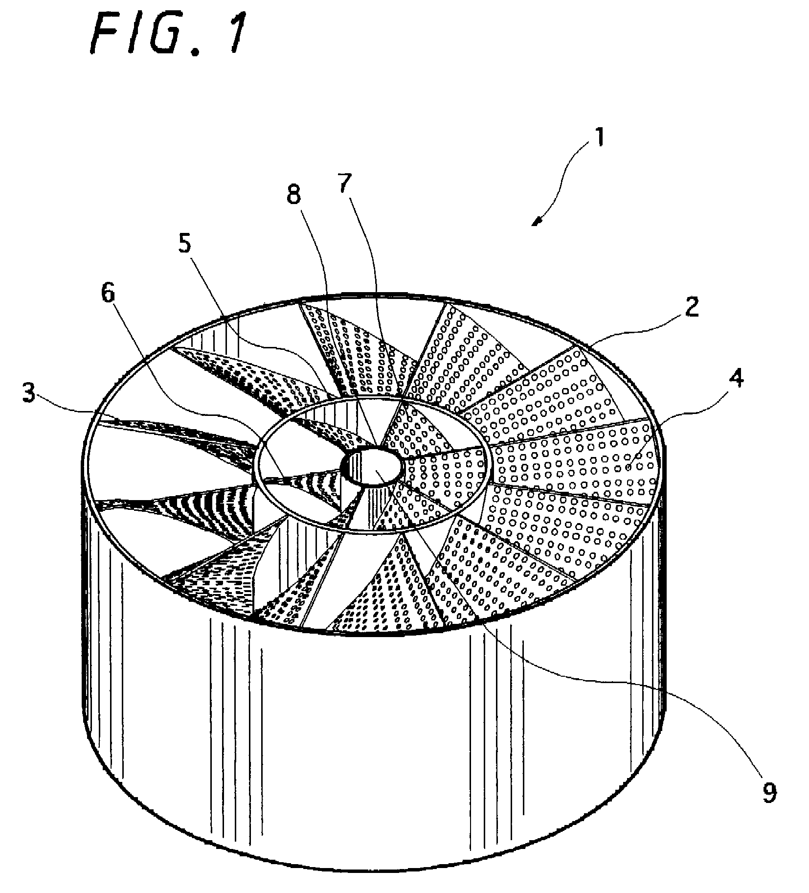
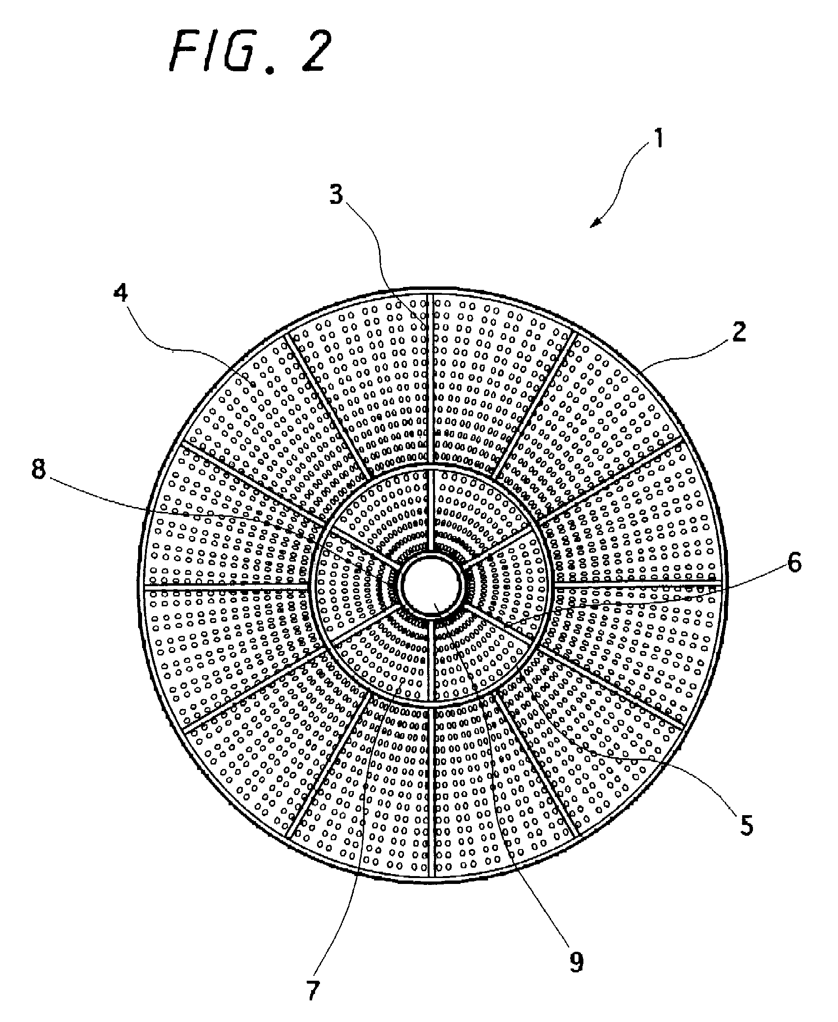
[0063]FIG. 1 is a perspective view of a 90° rightward rotation type (in the clockwise direction) mixing element showing a first embodiment according to the present invention, and FIG. 2 is a bottom view of the mixing element. A mixing element 1 has a cylindrical passage tube 2, and a plurality of spiral rightward rotation type first blades 3 provided in the passage tube 2. These first blades 3 are formed of a perforated object having a large number of perforations 4. On the inside of the first blades 3 is disposed a first inner cylindrical tube 5 shaped like a cylinder. The first inner cylindrical tube 5 is provided at a connecting portion of the first blades 3 by a necessary length in the axial center direction (in the longitudinal axial center direction), and is not disposed in any other places. In the first inner cylindrical tube 5 are provided a plurality of spiral rightward rotation type second blades 6 formed of a perforated object having a large number of perforations 7. On t...

embodiment 2

[0066]FIG. 3 is a partly-enlarged perspective view of a 90° rightward rotation type mixing element showing a second embodiment according to the present invention.

[0067]Similarly to the mixing element 1 shown in FIGS. 1 and 2, a mixing element 10 has a cylindrical passage tube 11 and a plurality of spiral rightward rotation type first blades 12 provided in the passage tube 11. The blades 12 are formed of a perforated object having a large number of perforations 13. On the inside of the blades 12 is disposed a first inner cylindrical tube 14 shaped like a cylinder, and to the outer circumferential portion of the inner cylindrical tube 14 is connected one end of each of the blades 12. The inner cylindrical tube 14 is formed of a perforated object having a large number of perforations 15. In the inner cylindrical tube 14 are provided a plurality of spiral rightward rotation type second blades 16 formed of a perforated object having a large number of perforations 17. On the inside of the...

embodiment 3

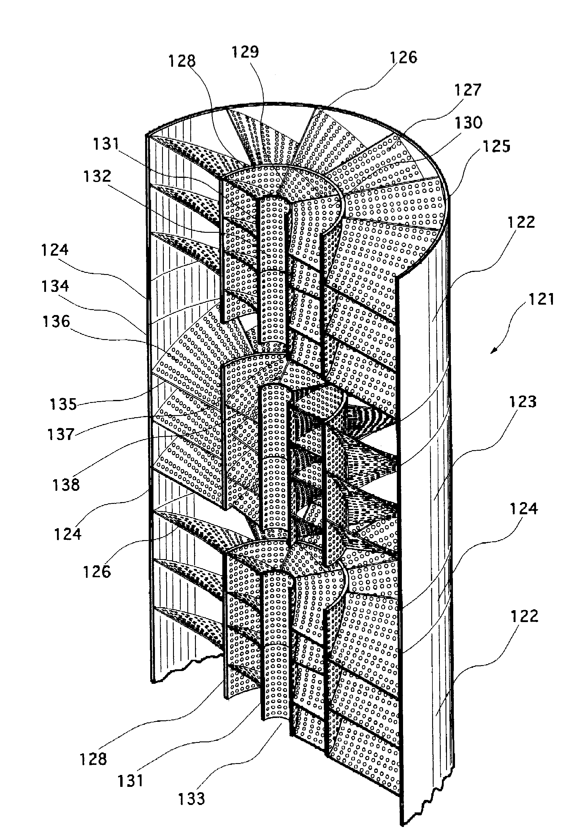
[0069]FIG. 4 is a perspective view of a mixing element showing a third embodiment according to the present invention. A mixing element 20 has a cylindrical passage tube 21 and a plurality of spiral rightward rotation type first blades 22 provided in the passage tube 21. The blades 22 are formed of a perforated object having a large number of perforations 23. On the inside of the blades 22 is disposed a first inner cylindrical tube 24 shaped like a cylinder. In the inner cylindrical tube 24 are provided a plurality of spiral leftward rotation type second blades 25 formed of a perforated object having a large number of perforations 26. On the inside of the blades 25 is disposed a second inner cylindrical tube 27 shaped like a cylinder to form an opening 28. The length of the passage tube 21 in the longitudinal axial center direction is made equal to or slightly greater than the length of the first blades 22.

[0070]Specifically, the mixing element 20 incorporates the first blades 22 of ...


PUM

PropertyMeasurementUnit
rotation angleaaaaaaaaaa

Abstract

A mixing element, which is produced at low cost, has high mixture agitation effectiveness, and is easily made large, and a static fluid mixer using the mixing element are provided. Further, a gas-liquid treatment apparatus with high treatment ability is provided. A mixing element 1 includes: a cylindrical passage tube 2 trough which fluid flows; a plurality of spiral rightward rotation type first blades 3 formed of a perforated object, which are provided in the passage tube 2; a first inner cylindrical tube 5 shaped like a cylinder and disposed inside the blades 3; a plurality of spiral rightward rotation type blades 6 provided in the inner cylindrical tube 5; and an opening 9 formed in the axial center portion of the blades 6. A static fluid mixer is formed by using at least one mixing, element 1 mentioned above.

Description

RELATED APPLICATION DATA[0001]The present application is a continuation-in-part of International Patent Application PCT / JP2004 / 01631 filed Feb. 16, 2004, which is fully incorporated herein by reference to the extent permitted by law.BACKGROUND OF THE INVENTION[0002]1. Field of the Invention[0003]The present invention relates to an improvement on a mixing element used in a static fluid mixer which mixes one or more kinds of fluids (liquids, gases, solids and mixtures of these) without a mechanically movable part, and also on a static fluid mixer using the mixing element.[0004]Static fluid mixers of this kind are used in mixture, agitation, extraction, distillation, gas absorption, solution, stripping, emulsification, heat exchange, dispersion, particulate mixture and the like.[0005]Further, static fluid mixers are used in many fields such as chemical industry, paper and pulp industry petrochemical industry, pharmaceutical industry, semiconductor industry, optical fiber manufacturing ...

Claims


Application Information

Patent Timeline
Patent Type & Authority Patents(United States)
IPC IPC(8): B01F3/04B01D53/18B01F5/06B01J19/30B01J19/32
CPCB01D53/18B01F3/0446B01F5/0612B01F5/0615B01J19/30B01J19/32B01J2219/30219B01J2219/30223B01J2219/30284B01J2219/3085B01J2219/32244B01J2219/32279B01J2219/3322B01J2219/3325B01F23/232B01F25/4312B01F25/43141B01F25/4317
Inventor KOJIMA, HISAO
Owner ANEMOS CO LTD
Why Eureka
Try Eureka