Method and apparatus for detection of inclusion in glass

a technology of inclusion and glass, applied in the direction of measuring devices, instruments, scientific instruments, etc., can solve the problems of glass panel inclusion and other defects, glass may shatter with potentially disastrous consequences, and the process is very slow

Inactive Publication Date: 2009-03-31
AGENCY FOR SCI TECH & RES
View PDF17 Cites 18 Cited by
  • Summary
  • Abstract
  • Description
  • Claims
  • Application Information

AI Technical Summary

Benefits of technology

[0012]Because of total internal reflection, light beam can travel a long distance within the panel. The method thus makes it possible to examine a relatively large area of the panel at a single time in contrast to the methods described above.
[0015]Furthermore, in contrast to the laser scattering technique described above, a much larger area of the panel (“field of view”) can be simultaneously tested than simply the area which is illuminated directly by the beam. Also, because of the total internal refraction, all of the light energy will be trapped inside of the panel. Only when the light strikes on an inclusion, the scattered light exits the path and thereby exits the panel. That is, the input light is used highly efficiently. The high efficiency of using the input light energy is advantageous for the two reasons. Firstly, most of the transparent panels, such as the toughed glass panels have a high absorption coefficient. Without the efficient use of the light energy, even with a high power light source, the field of view will still be very small, which results in a very slow inspection speed. Secondly, without the light leakage, the contrast of the images is high; all the defects are bright points like stars against the dark background of the other area of the panel.

Problems solved by technology

In particular, glass panels are subject to Nickel Sulphide (NiS) inclusions and other defects (faults).
If such checks are not carried out, the Nickel Sulphide inclusions may cause the toughened glass to fracture, and the glass may shatter with potentially disastrous consequences, both for people inside the high-rise building, and on the ground beneath.
Unfortunately, this process is very slow, due to the limited field of view (FOV) and depth of focus (DOF) of the observation process.
NiS inclusions are therefore difficult to observe against the generally high intensity of background light caused by reflections and scattering of light due to surface contamination and scratches.
Furthermore, many glass panels are printed with black dots to reduce the intensity of sunlight transmitted through them, and it is very difficult to observe the tiny dark inclusions in the shadow regions caused by the dots.
Thus, such techniques are not suitable for in-situ testing and are inconvenient even as a part of a QC mechanism.
However, in this technique only the area of the panel illuminated by the laser beam is measured.
Furthermore, most of the energy of the laser is not utilized, and either completely penetrates the glass panel, or is reflected by the glass surfaces.
Furthermore, contamination on either surface of the glass can cause light scattering, which induces noise in the measurement, and hence in the inclusion image obtained.
However, present technology only allows this technique to be used in a laboratory because it requires critical control of implementation conditions.

Method used


Image

  • Method and apparatus for detection of inclusion in glass
  • Method and apparatus for detection of inclusion in glass
  • Method and apparatus for detection of inclusion in glass

Examples


second embodiment

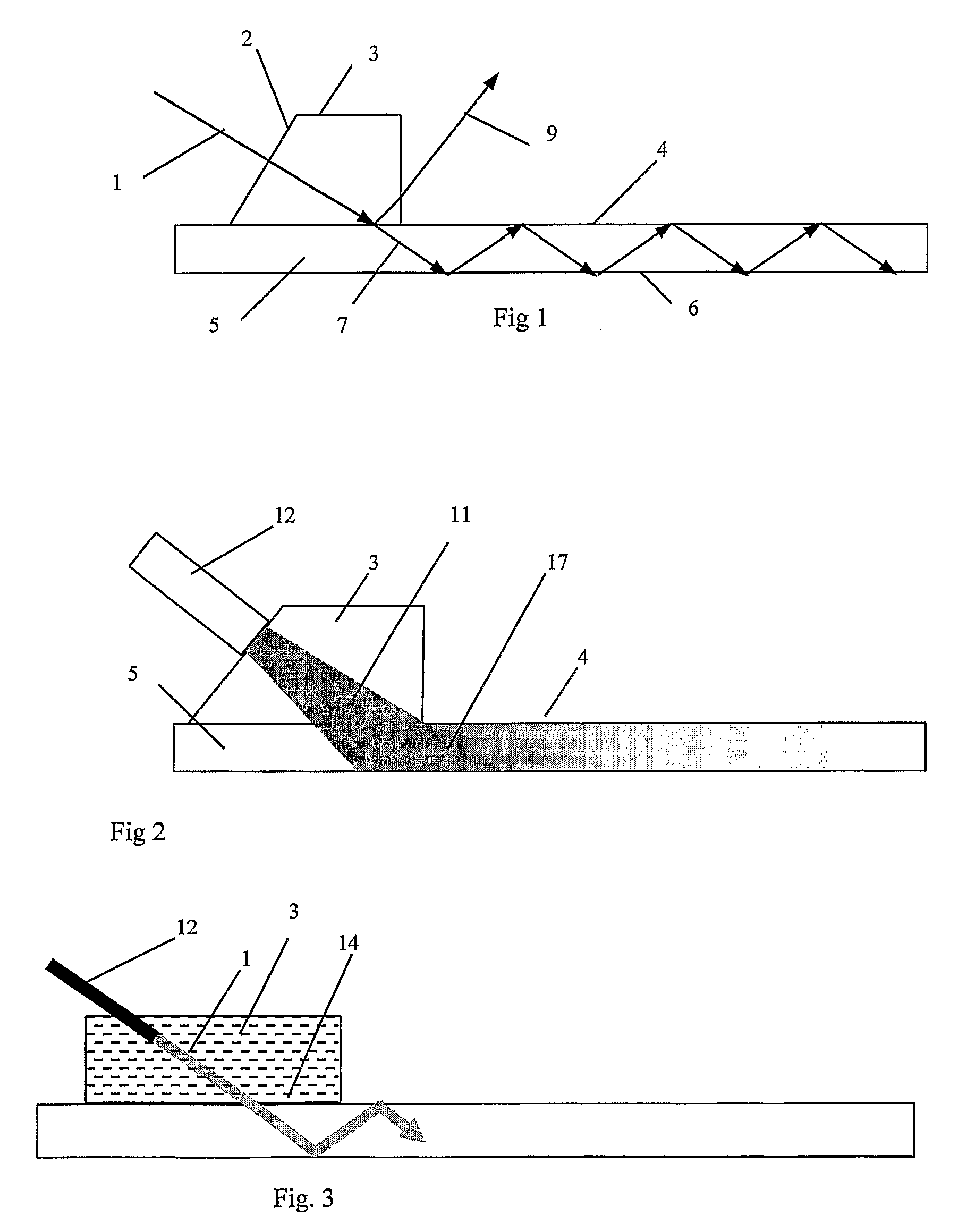
[0042]Alternatively, or additionally, the interface can include a liquid layer between the interface element 3 and the glass panel 5. The liquid may for example be water. This too increases the total contact area (i.e. reduces the possibility of air gaps between the interface and the glass panel 5). Furthermore the liquid may lubricate the contact between the interface element 3 and the glass panel 5, thereby making it easier to move the interface element 3 when it is desired to inspect a different area of the glass panel 5. This possibility is illustrated in the invention shown in FIG. 3. In this case the light source 12 is embedded in the interface element 3 (which does not have a prism-shaped cross-section). A layer 14 of liquid is present between the interface element 3 and the glass panel 5. A mechanism (not shown) can be provided for refreshing this liquid layer 9 (e.g. a reservoir and a pump for moving liquid from the reservoir from the pump). Water is preferred as the liquid...

fourth embodiment

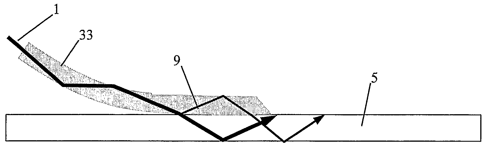
[0063]Whereas in the embodiments described above, the interface element 3 was generally prism-shaped in cross-section, it may alternatively be provided as a flexible sheet of deformable material (e.g. silicon rubber). Such the invention is shown in FIG. 7. The incident light beam 1 from the light source (not shown) enters one end of the interface element 33, and then propagates within it as a beam which is total internal reflected whenever it encounters the faces of the sheet 33 at a location where that surface is not in contact with the glass panel(in a way similar to the propagation of the light within the glass panel 5 in the embodiments described above).

[0064]When the beam 1 reaches a part of the interface element 33 which is touching the glass panel 5, the conditions for TIR no longer apply, because the difference between the refractive indices of the interface element 33 and the glass panel 5 is too low. Thus, the light passes into the glass. When the refractive indices of the...


PUM


Abstract

Inclusions in a transparent panel (5) are detected by placing a light transmissive interface (3) in contact with the panel (5), and transmitting a beam of light (1) through interface (3) into panel (5). Within the panel (5), the light beam (7) propagates along a path including total internal reflections at surfaces of panel (5). When the light beam (1) intercepts inclusions (10) or other defects at least some of it is scattered, and leaves the panel (5). This scattered light is then observed. Thus, a large zone of the panel (5) can be inspected, with light only being detected in the case that it arises from scattering by inclusions or other defects.

Description

RELATED APPLICATIONS[0001]This application claims priority to International Application No. PCT / SG2003 / 000294 filed Dec. 30, 2003, the teachings of which are incorporated herein by reference.FIELD OF THE INVENTION[0002]The present invention relates to methods and apparatus for inspection of transparent panels, and in particular for detecting faults, such as “inclusions”, in those panels. In particular, the invention relates to methods and apparatus which are suitable for use at a site where the transparent panel is located as a component of a building. However, the methods and apparatus may also have applications for quality control during a transparent panel manufacturing process.BACKGROUND OF INVENTION[0003]Transparent panels such as glass panels, especially panels of toughened glass, are widely employed in high-rise structures, and there is a need to inspect them to check for the presence faults. In particular, glass panels are subject to Nickel Sulphide (NiS) inclusions and othe...

Claims


Application Information

Patent Timeline
Patent Type & Authority Patents(United States)
IPC IPC(8): G01N21/00G01N21/55G01N21/958
CPCG01N21/552G01N21/958
Inventor FANG, ZHONGPINGLIU, TONGLI, XIANGREADING, IVAN
Owner AGENCY FOR SCI TECH & RES
Why Eureka
Try Eureka