Versatile high velocity integral vacuum furnace

a vacuum furnace and high-speed technology, applied in the field of low pressure, can solve the problems of high cost of cleaning the parts after they have been submerged in oil or salt, difficult to treat alloys, and difficulty in cleaning by hand, etc., and achieve high pressure, high-speed gas quench, and high-speed quenching capability

Active Publication Date: 2009-04-07
JONES WILLIAM R
View PDF20 Cites 6 Cited by
  • Summary
  • Abstract
  • Description
  • Claims
  • Application Information

AI Technical Summary

Benefits of technology

[0006]Applicants have found that a carburizing process including heating of steel parts in the presence of hydrogen prior to introduction of carburizing / diluent gas, can provide substantial improvement in carburizing in accordance with the present invention. The process uses a continuous cycle involving only one carburizing (boost) step and one diffusion step, and carburizing gas, preferably acetylene in the presence of a diluent carrier gas. The carburizing is desirably carried out in a furnace having high velocity quenching capability. The process according to the instant invention uses hydrogen as a pretreatment gas with significant soak time under heat, then, after the pretreatment, carburizing, followed by a high pressure, high velocity gas quench. The process provides a method that avoids the need for: (a) a highly programmed cycle; and (b) a complex sequential boost / diffuse process. The process also substantially avoids the requirement for sand blasting the steel parts prior to carburizing. The process is advantageously carried out in a unique, versatile furnace that provides a novel, high velocity, continuous flow gas quenching capability, and a furnace design, including an effective work zone configuration that contributes to more effective carburization. The entire process is advantageously accomplished in a single self-contained chamber of the unique furnace. The advantages of a high velocity gas quench are substantial. For example, with the gas quench there is far less work piece distortion and no oil cleanup following heat treatment. Also, the cost of having a separate chambers and equipment for moving workloads from one chamber to another are completely avoided.

Problems solved by technology

Some alloys are particularly difficult to treat and require post treatment, for example, quenching to finish the treatment.
The pieces thus moved and quenched have problems with distortion.
Also, cleaning the parts after they have been submerged in oil or salt is a costly challenge.
The mechanism for moving the work pieces at temperature undesirably adds significant cost, time and maintenance issues to the process.
Although, gas quenching avoids much of the finish product cleanup issues, it does not avoid the mechanical movement of the workload from one chamber to another.
It also is not without challenges in how it affects finished product quality.
With such hydrocarbon gases, however, soot produced in the carburizing chamber interferes with desired consistency of carburizing quality and adds significant cost to parts cleanup and furnace maintenance.
Achieving a uniform carburized “case”, a hardened, uniform surface layer, has been difficult and costly.
Uniformity has been a major challenge.
Atmosphere carburization suffers from the added problem of surface oxidation during heat treatment.

Method used


Image

  • Versatile high velocity integral vacuum furnace
  • Versatile high velocity integral vacuum furnace
  • Versatile high velocity integral vacuum furnace

Examples


Embodiment Construction

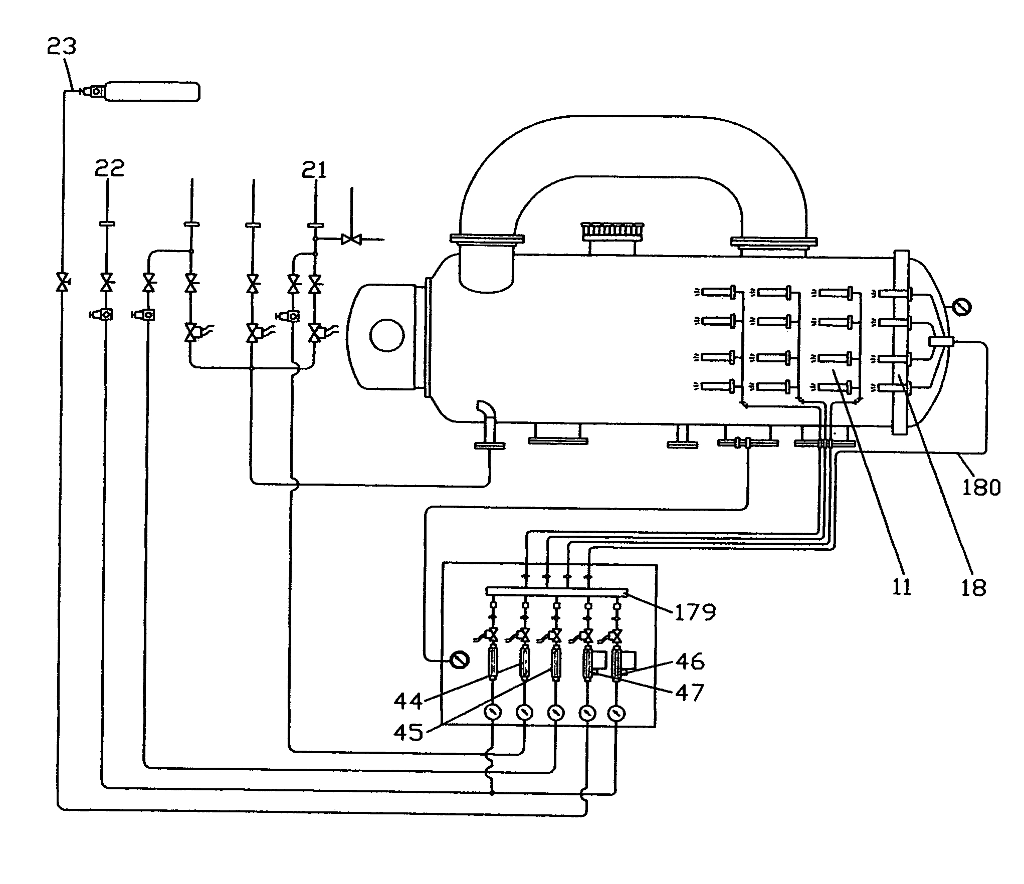
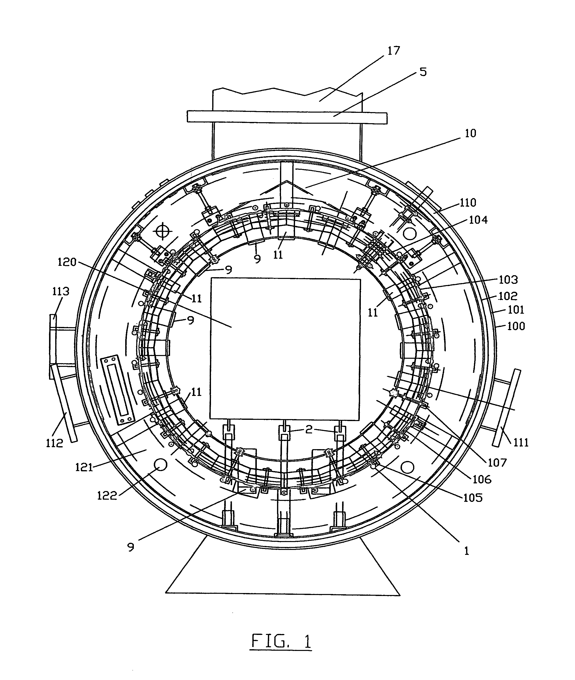
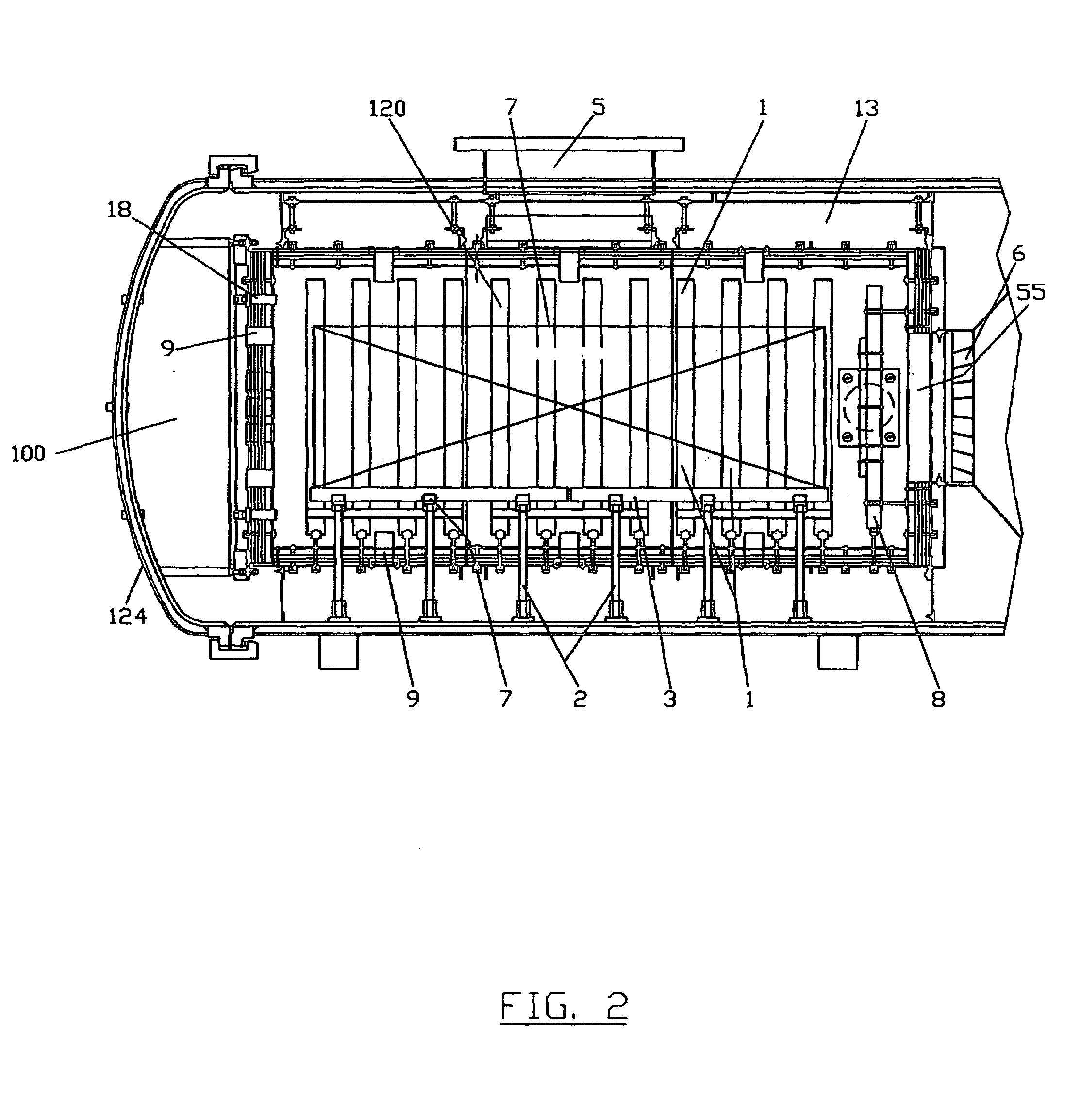
[0013]A front, cross section view (looking toward the door end) of high temperature, vacuum furnace 100, is depicted in perspective in FIG. 1 revealing outer furnace wall 101 and inner wall 102 which form the radial boundaries of furnace water jacket 110 used for cooling the furnace. The outer chamber of furnace 100, thus, is a cylindrical double walled water-cooled vessel, and is manufactured from 304 stainless steel. The water jacket width is approximately 1″ maximum, with large oversized water inlet and exit ports (not shown) located around the chamber to allow for convenient periodic flushing of the water jacket to reduce sediment build-up. Inner wall 102 also forms the outer wall of spacious gas plenum chamber 13 (see FIG. 2), a large annular cavity important to high velocity (very rapid) quenching. Cylindrical shaped heating elements 1, each desirably graphite resistance heating elements, each forming a complete circle, are supported in place by molybdenum standoff assemblies ...


PUM

PropertyMeasurementUnit
pressureaaaaaaaaaa
pressureaaaaaaaaaa
speedsaaaaaaaaaa

Abstract

Versatile vacuum furnace (also having high internal pressure capability) designed for facilitating directed gas flow has a treating chamber including a long, low profile work zone configuration, and powerful gas recirculation equipment with unique structure supporting gas flow patterns that facilitate high velocity gas flow into and through the chamber. The furnace can be used for single or multiple step metal treatment processes. An entire multi step process, for example, carburizing, including gas quenching, is accomplished relatively quickly in a single self-contained chamber of the furnace.

Description

BACKGROUND OF THE INVENTION[0001]1. Field of the Invention[0002]The present invention relates to low pressure carburization and other heat treating processes applied to metal alloy parts and more particularly steel parts and to high temperature capable furnaces having the capability of providing in the same furnace chamber alternatively, low pressure (vacuum) and high pressure (gas quench) environments for such processes.[0003]2. Background Art[0004]Vacuum (low pressure) heat treating (carburization) of steel or high alloy-content steels has been accomplished over past decades using various heat treating processes. Some alloys are particularly difficult to treat and require post treatment, for example, quenching to finish the treatment. Some metals are more difficult to treat (for example alloys such as AISI grade 4140, 4340, 8620, and 9310). Work pieces containing such alloys are currently heat treated and then moved to an oil or salt bath quench. That is, the work pieces are moved...

Claims


Application Information

Patent Timeline
Patent Type & Authority Patents(United States)
IPC IPC(8): C21D1/06
CPCC21D1/06
Inventor JONES, WILLIAM R.
Owner JONES WILLIAM R
Why Eureka
Try Eureka