Method for removing mercury in exhaust gas

a technology of exhaust gas and mercury, which is applied in the direction of physical/chemical process catalysts, emission prevention, separation processes, etc., can solve the problems of increasing utility costs and occurrence of material corrosion, increasing catalyst performance, and catalyst itself being closed by the adherend, etc., to achieve enhanced catalyst durability and reduce catalyst amount

Inactive Publication Date: 2009-04-21
MITSUBISHI HITACHIPOWER SYST LTD
View PDF2 Cites 40 Cited by
  • Summary
  • Abstract
  • Description
  • Claims
  • Application Information

AI Technical Summary

Benefits of technology

[0007]In view of the above problems, the inventors conducted studies earnestly to develop a method for removing mercury in exhaust gas, in which even if NH3 leaks to the downstream side of the denitrification apparatus, hindrance to reaction due to N

Problems solved by technology

However, when mercury is converted to mercury chloride by using the denitrification catalyst, the conversion temperature is limited to 300 to 450°, so that in the case of coal with a low Cl content, it is necessary to supply HCl into exhaust gas to maintain the rate of conversion to mercury chloride, which presents problems of increased utility cost and occurrence of material corrosion.
However, when metallic mercury is converted to mercury chloride by using a mercury oxidation catalyst at a low temperature, excess NH3

Method used


Image

  • Method for removing mercury in exhaust gas
  • Method for removing mercury in exhaust gas
  • Method for removing mercury in exhaust gas

Examples


example 1

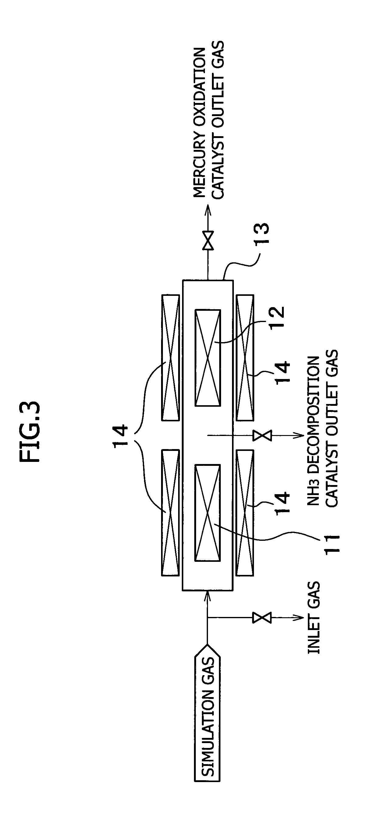
[0058]A test was carried out to evaluate the oxidation rate of mercury and the decomposition rate of ammonia by using an apparatus for removing mercury in exhaust gas which is shown in FIG. 3.

[0059]In the apparatus of this example 1, H2O, CO2, O2, NH3 and HCl were added to N2 gas, and the vapor of metallic mercury was mixed to prepare a simulation gas. The simulation gas was introduced into a reactor 13, and was allowed to pass through an NH3 decomposition catalyst 11 and a mercury oxidation catalyst 12 provided in the reactor 13. For the catalysts, the temperature thereof was controlled by an electric heater 14. An inlet gas, an outlet gas of the NH3 decomposition catalyst 11, and an outlet gas of the mercury oxidation catalyst 12 were sampled.

[0060]The test conditions were as described below: the content of added gases were H2O: 7%, CO2: 12%, O2: 5%, NH3: 10 ppm, and HCl: 10 ppm, the mercury concentration was Hg: 30 μg / m3N, the reactor temperature was 350° C. at ordinary pressure,...

example 2

[0064]A test was carried out to evaluate the oxidation rate of mercury and the decomposition rate of ammonia by using an apparatus for removing mercury in exhaust gas which is shown in FIG. 4.

[0065]In the apparatus of this example 2 as well, H2O, CO2, O2, NH3 and HCl were added to N2 gas, and the vapor of metallic mercury was mixed to prepare a simulation gas. The simulation gas was first introduced into a reactor 16, and was allowed to pass through the NH3 decomposition catalyst 11 provided in the reactor 16, and the temperature of the catalyst was controlled by the electric heater 14. The gas coming out of the reactor 16 passed through a cooler 15, and then was introduced into a next reactor 17. The gas was allowed to pass through the mercury oxidation catalyst 12 provided in the reactor 17, and the temperature of the catalyst was controlled by the electric heater 14. An inlet gas, an outlet gas of the NH3 decomposition catalyst 11, and an outlet gas of the mercury oxidation catal...


PUM

PropertyMeasurementUnit
Temperatureaaaaaaaaaa

Abstract

The present invention provides a system for removing mercury in exhaust gas, in which mercury is removed from exhaust gas of a boiler, characterized in that between a denitrification apparatus and a wet type desulfurization apparatus, an NH3 decomposition catalyst and a mercury oxidation catalyst are provided, and mercury having been oxidized into mercury chloride is removed by the wet type desulfurization apparatus. Also, it provides a method for removing mercury in exhaust gas, characterized in that the mercury removing method includes an NH3 decomposition process and a mercury oxidation process, which are provided between the denitrification process and a wet desulfurization process, and mercury having been oxidized into mercury chloride is removed in the wet desulfurization process.

Description

TECHNICAL FIELD[0001]The present invention relates to a mercury removing method for removing mercury from exhaust gas of a boiler and a mercury removing system therefor. More particularly, it relates to a mercury removing method suitable for removing mercury contained in exhaust gas with a low Cl content discharged from a coal-fired boiler or the like and a system for implementing the said method.BACKGROUND ART[0002]Conventionally, it has been thought that mercury exists in exhaust gas in forms of metallic mercury insoluble in water and mercury chloride soluble in water. If metallic mercury can be converted to mercury chloride in the presence of a catalyst such as a denitrification catalyst, mercury can be removed by a desulfurization apparatus on the downstream side (for example, see Japanese Patent Provisional Publication No. 10-230137 (No. 230137 / 1998)).[0003]However, when mercury is converted to mercury chloride by using the denitrification catalyst, the conversion temperature i...

Claims


Application Information

Patent Timeline
IPC IPC(8): B01D53/52B01D53/64B01D53/86B01J23/22B01J23/30F23J15/00
CPCB01D53/64F23J15/006B01D2257/406B01D2257/602F23J2215/60F23J2219/10F23J2219/40
Inventor HONJO, SHINTAROIIDA, KOZOOKINO, SUSUMUKOBAYASHI, KAZUTOOKADA, KENICHIKAMIYAMA, NAOYUKINOJIMA, SHIGERUTAKEUCHI, YASUHIROOHISHI, TSUYOSHI
Owner MITSUBISHI HITACHIPOWER SYST LTD
Why Eureka
Try Eureka