Method and system for imaging an object

a technology of object image and image, applied in the field of method and system, can solve the problems of distinctly prolonged recording time, loss of resolution, and improvement of quality, and achieve the effects of improving measuring accuracy, free-hand recording, and reducing the loss of resolution

Active Publication Date: 2009-04-21
SIRONA DENTAL SYSTEMS
View PDF25 Cites 60 Cited by
  • Summary
  • Abstract
  • Description
  • Claims
  • Application Information

AI Technical Summary

Benefits of technology

[0020]Recording of the test object can take place without substantial loss of time during the calibration of the system, which is in any case necessary for computation of contrast or relief images from the phase related images. However, it may be also carried out separately, if desired, so that prior to each measurement of an object to be imaged the most favorable computation scheme can be selected.
[0021]The method of the invention is of particular advantage for those systems in which the object to be imaged and the camer

Problems solved by technology

For example, any deviation from the linear motion of the optical grid leads to noise at 2-fold grid frequency, any change in the intensity of the grid illumination to noise at 1-fold grid frequency, and deviations from the linearity between the light signal and electrical signal leads to noise at 4-f

Method used


Image

  • Method and system for imaging an object
  • Method and system for imaging an object
  • Method and system for imaging an object

Examples


Embodiment Construction

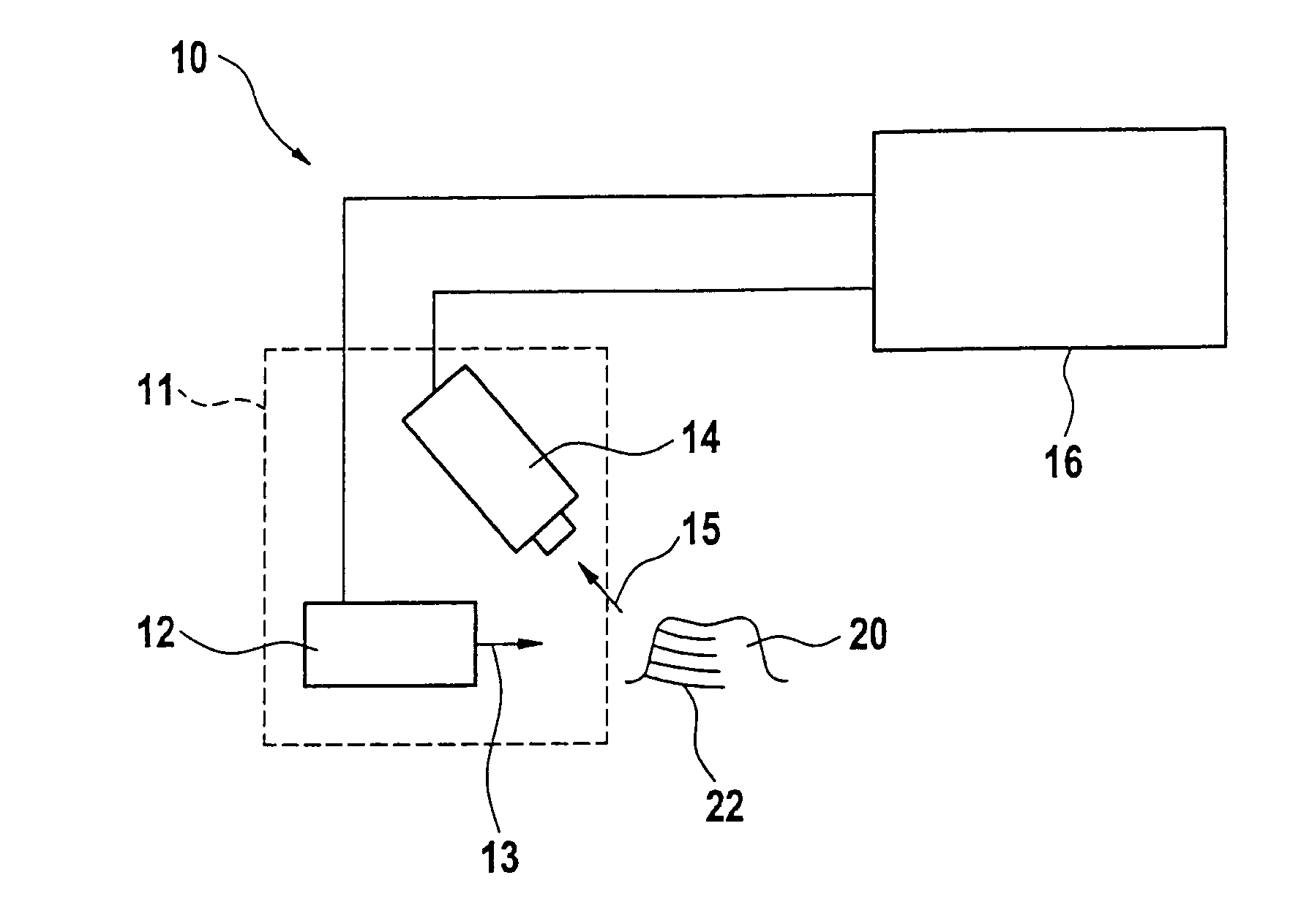
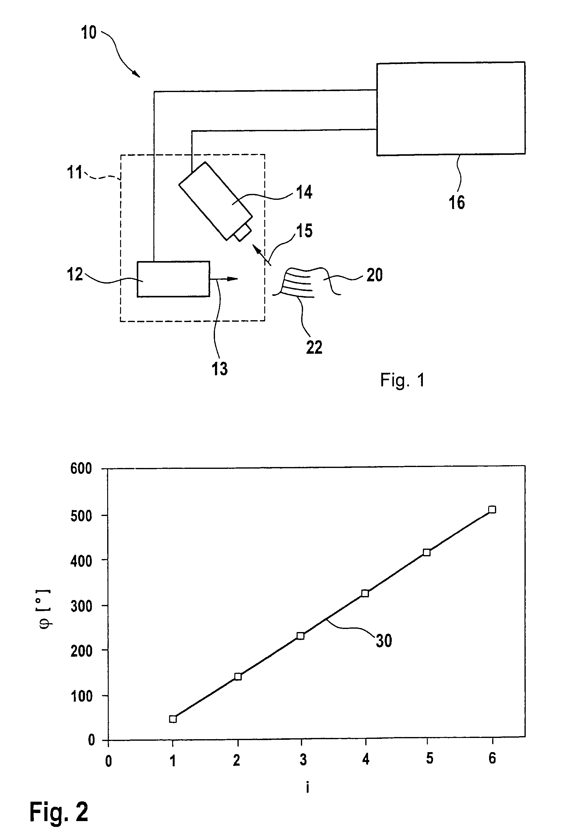
[0032]FIG. 1 is a diagrammatic representation of a recording device designated by the reference numeral 10 and adapted to operate according to the principle of phase shift triangulation. The projecting device 12 produces a grid of light having parallel grid lines projected on to an object to be imaged, in the present example a tooth 20. By reason of the three-dimensional surface texture of the tooth 20, the lines of light in the grid on the tooth appear to be bent and unevenly spaced. The image 22 projected via the projection ray trajectory 13 is recorded (videographed) at an angle of parallax by means of a two-dimensional camera 14 disposed in the trajectory of observation 15 and is passed on to an evaluation unit 16 for evaluation. The projecting device 12 and the camera 14 may be combined to form a structural unit 11, as will be later shown in FIG. 5 in the case of an intraoral camera.

[0033]After the first basic image R1 has been recorded, further basic images showing defined pha...


PUM


Abstract

In a method of imaging an object, for dental purposes, comprises:
  • a) projecting a striped pattern on to the object to be imaged,
  • b) recording the projected striped pattern as a basic image (Ri) with a camera, steps a) and b) being carried out at a number of different positions of the phase relationship of the striped pattern, and
  • c) computing an image of the object from the plurality of mutually out-of-phrase basic camera images. Provision is made for suppression of periodic disturbances in that, in step c),
  • c1) at least two groups of basic images (R1, R2, . . . , Rn; R2, R3, . . . , Rn+1) are formed from the basic camera images (R1, . . . , Rm),
  • c2) a phase related image (Pj) of the object to be imaged (20) is computed from each group of basic images (R1, R2, . . . , Rn; R2, R3, . . . , Rn+1),
  • c3) the computed phase related images (P1, P2) are averaged such that a phase related image (P) having a reduced amount of noise is formed, and that
  • c4) an image of the object is computed from the phase related image (P) having a reduced amount of noise.

Description

TECHNICAL FIELD[0001]The invention relates to a method of creating an image of an object, particularly for dental purposes, comprising the following method steps: a) projecting a striped pattern on to the object to be imaged, b) recording the projected striped pattern as a basic image with a camera, the steps a) and b) being carried out at a number of different positions of the phase relationship of the striped pattern, and c) computing an image of the object to be imaged from the plurality of mutually out-of-phase basic camera images. Suitable images are, in particular, relief images or contrast images.BACKGROUND OF THE INVENTION[0002]Direct optical three-dimensional surveying of one or more teeth in the mouth of a patient can provide digital construction data for the computer-controlled production of dentures without using a dental impression. Such a three-dimensional representation, known as an “optical impression” in analogy to physical molding, can be made with one or more came...

Claims


Application Information

Patent Timeline
IPC IPC(8): G06K9/00A61C3/00G01B11/24G06K9/36G06K9/40A61B1/24A61B5/107A61B6/00A61C13/00G01B11/25H04N13/02
CPCA61B1/24A61B5/1077A61B5/4547A61B5/7203G01B11/2527
Inventor SCHWOTZER, AXEL
Owner SIRONA DENTAL SYSTEMS
Why Eureka
Try Eureka