Combined positron emission tomography and magnetic resonance tomography unit

a technology of positron emission tomography and magnetic resonance tomography, which is applied in tomography, instruments, applications, etc., can solve the problems of comparatively poor spatial resolution of pet, and achieve the effect of saving space and tim

Inactive Publication Date: 2009-04-21
SIEMENS HEALTHCARE GMBH
View PDF25 Cites 50 Cited by
  • Summary
  • Abstract
  • Description
  • Claims
  • Application Information

AI Technical Summary

Benefits of technology

[0008]It is one possible object of the invention to specify a combination of a positron emission tomography unit and a magnetic resonance tomography unit that saves space and in which the PET and MRT imaging do not interfere with one another. Furthermore, it is another possible object to specify a method that saves time and in which the PET and MRT imaging do not interfere with one another.

Problems solved by technology

However, PET has a comparatively poor spatial resolution of, for example, approximately 5 mm that can no longer be raised without additional radiation loading.

Method used


Image

  • Combined positron emission tomography and magnetic resonance tomography unit
  • Combined positron emission tomography and magnetic resonance tomography unit
  • Combined positron emission tomography and magnetic resonance tomography unit

Examples


Embodiment Construction

[0050]Reference will now be made in detail to the preferred embodiments of the present invention, examples of which are illustrated in the accompanying drawings, wherein like reference numerals refer to like elements throughout. Mutually corresponding parts are provided with the same reference symbols in FIGS. 1 to 4.

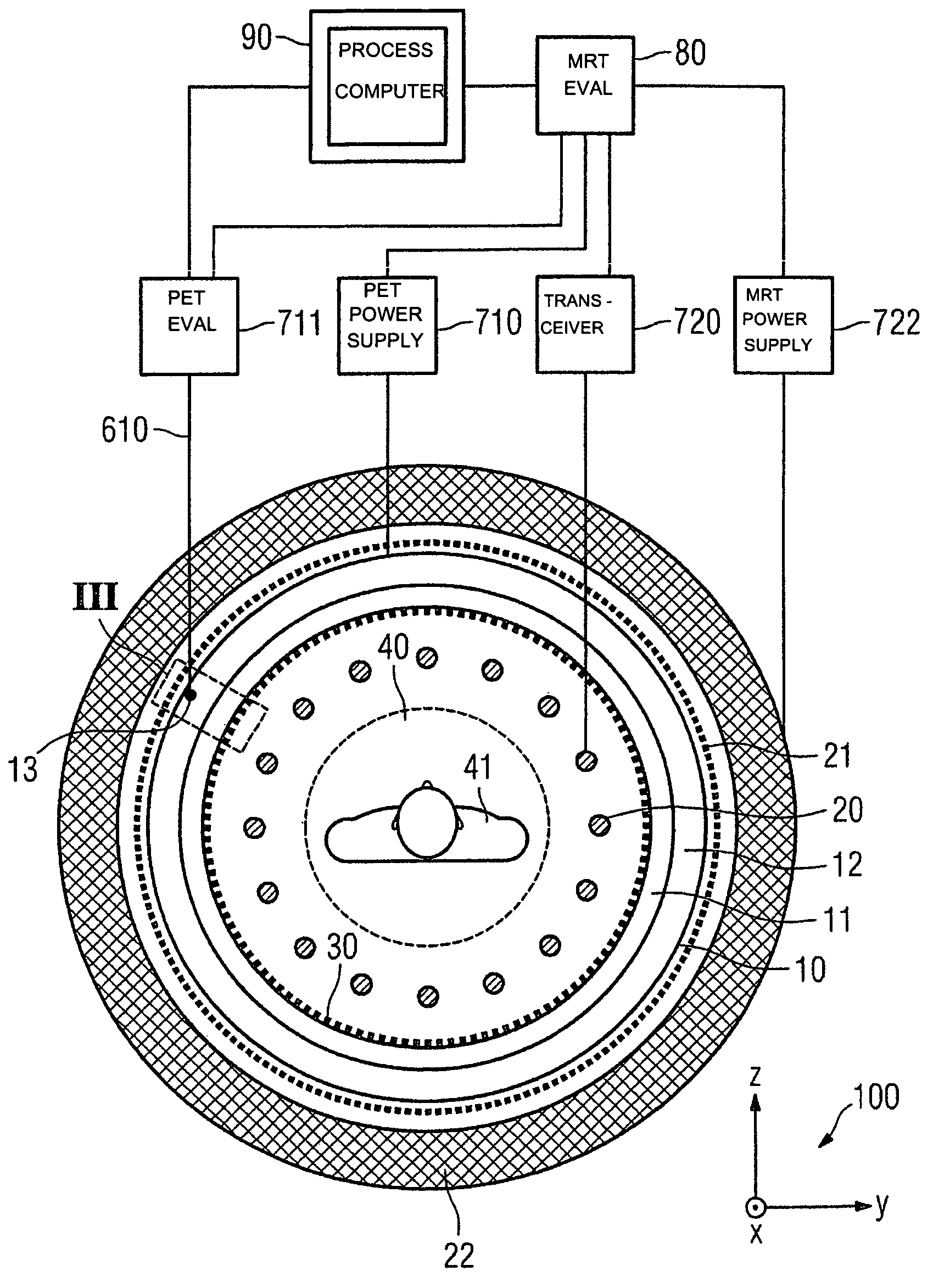
[0051]FIG. 1 is a schematic of a cross section of a combined PET / MRT unit for imaging an examination object 41 in an examination space 40. The combined PET / MRT unit is composed of an MRT unit and a PET unit with an integrated PET unit part 10.

[0052]For the sake of clarity, the obligatory coils in an MRT unit, which generate a fundamental magnetic field in the examination space 40 are not illustrated. In order to generate independent, mutually perpendicular magnetic field gradients of directions x, y, z in accordance with a coordinate system 100, an MRT unit comprises a gradient coil system 22, which is illustrated here only in a simplified schematic fashion. In addition...


PUM


Abstract

A combined PET / MRI tomography unit has a PET unit with a unit part assigned to the examination space, and a first evaluation unit for evaluating the PET electric signals. The unit part has a gamma ray detector. The combined unit has an MRI unit and a second evaluation unit for evaluating MRI signals. The MRI unit has a high frequency antenna as well as a gradient coil system, the high frequency antenna device being arranged nearer to the examination space than the gradient coil system, as well as a high frequency shield arranged between the gradient coil system and the high frequency antenna device. The PET unit part is arranged between the high frequency shield and the high frequency antenna device. A shielding cover for the high frequency antenna device faces the high frequency antenna device. The shielding cover is opaque to high frequency radiation.

Description

CROSS REFERENCE TO RELATED APPLICATIONS[0001]This application is based on and hereby claims priority to German Application No. 10 2005 015 070.5 filed on Apr. 1, 2005, the contents of which are hereby incorporated by reference.BACKGROUND OF THE INVENTION[0002]The invention relates to a combination of positron emission tomography and magnetic resonance tomography units (PET / MRT unit) for imaging an examination object in an examination space. The invention also relates to a method for imaging an examination object in an examination space by a combined positron emission tomography and magnetic resonance tomography unit.[0003]Magnetic resonance tomography (MRT) and positron emission tomography (PET) are nowadays indispensable methods for the accurate diagnosis of many diseases and medical disturbances. It is possible hereby to image affected organs and organ parts exactly in three dimensions and, moreover, to track the physiological and biochemical processes in the affected organs or or...

Claims


Application Information

Patent Timeline
Patent Type & Authority Patents(United States)
IPC IPC(8): A61B5/055
CPCA61B6/037G01R33/481G01T1/1603G01T1/2985A61B6/4417A61B6/5247
Inventor KRIEG, ROBERTKUTH, RAINERLADEBECK, RALFOPPELT, RALPHRENZ, WOLFGANGSCHMIDT, SEBASTIANVESTER, MARKUS
Owner SIEMENS HEALTHCARE GMBH
Why Eureka
Try Eureka