Power source device for working machine

a technology for working machines and power sources, applied in the direction of electric devices, machines/engines, electric generator control, etc., can solve the problems of obstructing effective use of excessively small power generation, and excessive power generation over the performance of the power storage device, so as to reduce the charge amount and reduce the discharge power. , the effect of increasing the charge power

Active Publication Date: 2009-04-28
KOBELCO CONSTR MASCH CO LTD +1
View PDF17 Cites 46 Cited by
  • Summary
  • Abstract
  • Description
  • Claims
  • Application Information

AI Technical Summary

Benefits of technology

[0019]According to the invention, the charge power and the discharge power of the power storage device, and the power of the engine are set in accordance with the charge amount of the power storage device. Specifically, as the charge amount reduces, the charge power is increased, and the discharge power is decreased, while the engine power is increased. Then, the power distribution between the engine and the power machine is performed based on the charge power, the discharge power, the engine power, and the required actuator power. This allows for maintaining the charge amount of the power storage device in a predetermined range, i.e. a range capable of securing effective use of the performance of the power storage device, and preventing the power storage device from excessive charging and excessive discharging to suppress degradation of the power storage device.

Problems solved by technology

This may cause, under a certain load condition, an excessively small power generation, or an excessively large power generation over the performance of the power storage device.
The result may obstruct effective use of the performance of the power storage device, and degrade the power storage device.

Method used


Image

  • Power source device for working machine
  • Power source device for working machine
  • Power source device for working machine

Examples


first embodiment

[0031](See FIGS. 1 through 9)

[0032]The first embodiment shows a case using a battery as an electric power storage device i.e. a secondary cell such as a lithium ion cell.

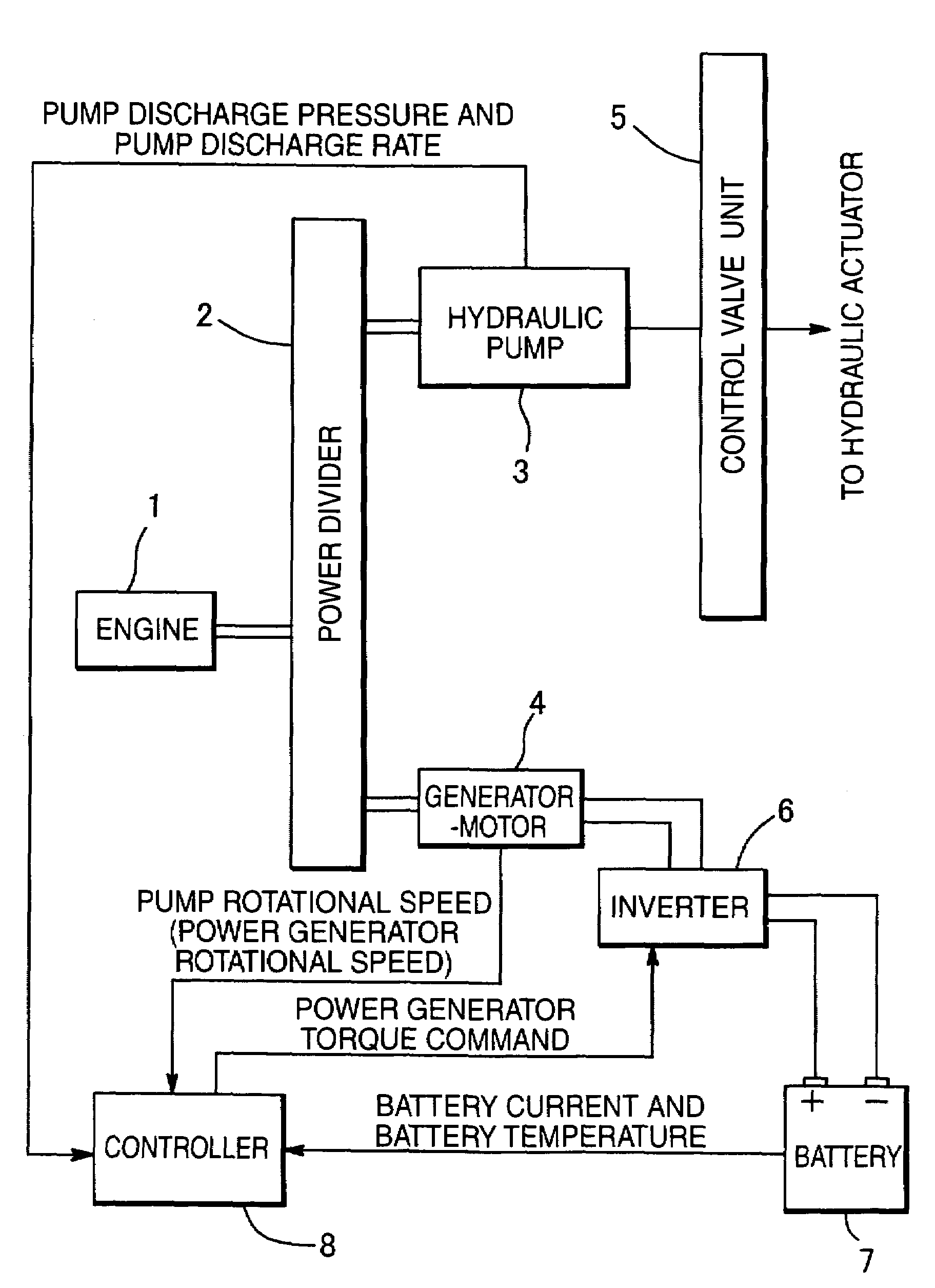
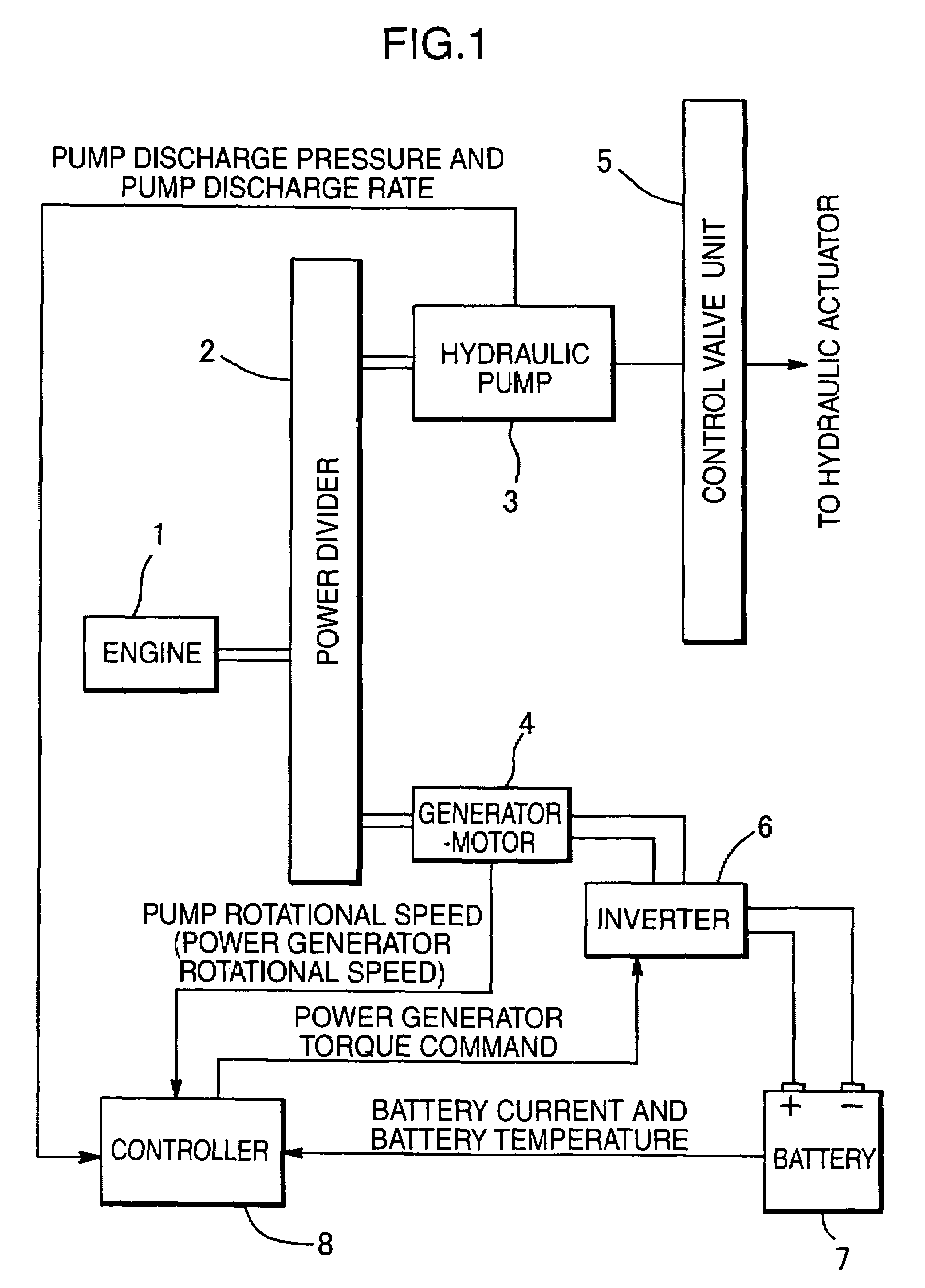
[0033]As shown in FIG. 1, a hydraulic pump 3, and a generator-motor 4 which is a power machine functioning as a generator and an electric motor, is connected in parallel to a engine 1 via a power divider 2 to be driven by the engine 1.

[0034]The hydraulic pump 3 is connected to unillustrated hydraulic actuators (e.g. in a power shovel, respective cylinders for a boom, an arm, and a bucket; a hydraulic motor for running) via control valves 5, which are hereinafter collectively shown although the control values are individually provided for the respective actuators. The hydraulic actuators are driven by hydraulic oil supplied from the hydraulic pump 3. FIG. 1 shows a case where the single hydraulic pump 3 is connected to the engine 1, but there may be another case where plural hydraulic pumps are connected to the engin...

second embodiment

[0078](See FIGS. 10 and 11)

[0079]The second embodiment uses a capacitor 15 as a power storage device.

[0080]The basic system configuration of the power storage device in the second embodiment is substantially the same as that in the first embodiment except for the following.

[0081](a) the capacitor 15 is used in place of the battery 7 in FIG. 1.

[0082](b) a converter 16 is provided as a controlling device for the capacitor 15.

[0083](c) a voltage sensor 17 is provided on a direct-current (DC) circuit connecting an inverter 6 and the converter 16 to detect a DC voltage.

[0084]A controller 18 in the second embodiment is different from the controller 8 in the first embodiment (FIGS. 1 and 2) in only that DC voltage controlling means 19 is added to the controller 18 as shown in FIG. 11. Capacitor charge amount detecting means 20, capacitor temperature detecting means 21, and capacitor power setting means 22 in FIG. 11 respectively correspond to the battery charge amount detecting means 9, th...


PUM


Abstract

Power distribution of an engine and an electric power storage device is determined according to a charge amount of the power storage device, and the charge amount of the power storage device is maintained in an adequate range. A power source device for working machines includes a hydraulic pump, a generator-motor, an engine, serving as a common power source, to which the hydraulic pump and the generator-motor are connected parallel, and a battery, serving as an electric power storage device, for storing a power thereof by the generator function of the generator-motor. The generator-motor is driven by a discharge power of the battery to perform the motor function. Using a controller, the power distribution of the engine and the generator-motor is determined based on the required actuator power, the charge power and the discharge power of the battery which are set according to the battery charge amount in such a way that the battery charge amount is maintained in a predetermined range, and on the preset engine power.

Description

TECHNICAL FIELD[0001]The present invention relates to a power source device for a hybrid working machine using an engine power and an electric power.BACKGROUND ART[0002]There is well known a hybrid working machine e.g. a power shovel using a parallel driving system (see Japanese Unexamined Patent Publication No. 10-42587)[0003]In the parallel driving system, a hydraulic pump, and a power machine functioning as a generator and an electric motor are connected in parallel to an engine serving as a common power source. The hydraulic pump drives a hydraulic actuator, while the power machine functions as a generator to store power in a power storage device. Also, the power discharged from the power storage device, when needed, allows the power machine to function as a motor for assistance of the engine.[0004]As the power machine, there may be used a single machine which functions both as a generator and an electric motor, or individual machines, one of which is a generator and the other i...

Claims


Application Information

Patent Timeline
Patent Type & Authority Patents(United States)
IPC IPC(8): H02J11/00B60K1/00F02D29/04B60K6/12B60L50/16B60W10/06B60W10/30B60W20/00H02P9/04
CPCB60K6/12B60L1/003B60L3/0046B60L11/14B60L11/187B60L11/1872B60W10/06B60W10/08B60W10/26B60W10/30B60W20/00B60K6/48Y02T10/70B60W2510/244B60W2510/246B60Y2200/41Y02T10/6208Y02T10/6221Y02T10/6286Y02T10/7005Y02T10/705Y02T10/7077B60L50/16B60L58/24B60L58/25B60L58/15B60L58/14Y02T10/62Y02T10/7072F01B23/10
Inventor KAGOSHIMA, MASAYUKISORA, TOSHIOKOMIYAMA, MASAYUKI
Owner KOBELCO CONSTR MASCH CO LTD
Why Eureka
Try Eureka