Differential peak detector

Active Publication Date: 2009-04-28
MARVELL ASIA PTE LTD
View PDF7 Cites 15 Cited by
  • Summary
  • Abstract
  • Description
  • Claims
  • Application Information

AI Technical Summary

Benefits of technology

[0015]By outputting a differential signal for differential amplification, the multiplexer provides the advantage of a high signal-to-noise ratio because noise coupled to the signal cancels out. For example, the multiplexer outputs a positive output

Problems solved by technology

However, the accuracy of conventional peak detectors is limited, since the single-end peak detector architecture suffers from a low signal-to-noise ratio.
Moreover, the output of conventional peak detectors is sensitive to input signal DC level variation caused by power supply variation and other noise sources.
Furthermo

Method used


Image

  • Differential peak detector
  • Differential peak detector
  • Differential peak detector

Examples


Embodiment Construction

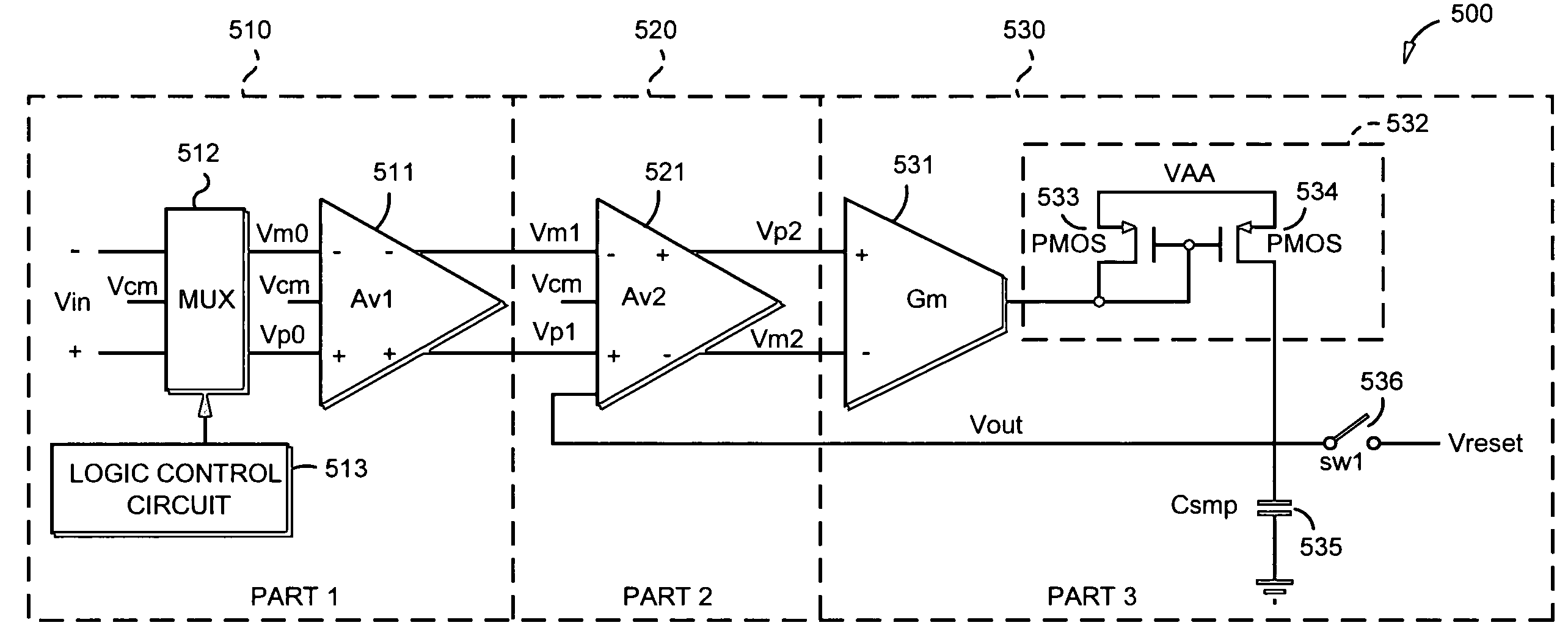
[0036]FIG. 5 is a block diagram of a differential peak detector according to a preferred embodiment of the invention. Differential peak detector 500 is constructed from three fundamental components: differential amplifier 511, differential amplifier 521, and transconductor amplifier 531. Differential amplifier 511 is constructed to differentially amplify an input signal and output a common mode output whose common mode level is substantially the same as a common mode voltage. Differential amplifier 521 is constructed to output a difference between the common mode output of differential amplifier 511 and a feedback from the output signal across sampling capacitor 535. Transconductor amplifier 531 is constructed to control charging of sampling capacitor 535 based on the output of differential amplifier 521. More detailed explanations are provided hereinbelow.

[0037]Differential amplifier 511 forms stage 510 of differential peak detector 500, along with MUX 512 and logic control circuit...


PUM


Abstract

Differential peak detection for outputting a signal indicative of a peak value of an input signal. The input signal is differentially amplified using common mode feedback and a common mode output is thereby output, wherein common mode level of the common mode output is substantially the same as a common mode voltage. The common mode output of such differential amplification is coupled to an input of a first common source input pair, and the common mode voltage and a feedback from the output signal across a sampling capacitor is coupled to an input of a second common source input pair. A summation of respective outputs of the first and second common source input pairs is coupled to an input of a transconductance stage, wherein an output of the transconductance stage controls charging of the sampling capacitor. In this manner, a more accurate output signal is provided.

Description

CROSS-REFERENCE TO RELATED APPLICATION[0001]This application claims the benefit of U.S. Provisional Patent Application No. 60 / 862,260, filed Oct. 20, 2006, the contents of which are hereby incorporated by reference as if fully stated herein.FIELD OF THE INVENTION[0002]The present invention relates to a detector for detecting a peak level of a voltage signal used in an apparatus.BACKGROUND OF THE INVENTION[0003]In processing signals used by an electronic apparatus, it is often useful to detect the peak level of a signal. This is particularly true of an electrical apparatus that is designed to read and write signals to and from a data storage medium, such as, for example, a DVD read / write device. For such apparatuses, it is important that signal peaks are accurately detected.[0004]A peak detector is an analog circuit adapted to detect the peak levels of a signal. Conventional peak detectors detect single-end peaking signals by charging or discharging a sampling capacitor.[0005]However...

Claims


Application Information

Patent Timeline
IPC IPC(8): H03K5/153
CPCH03K5/1532
Inventor LUO, QIANG
Owner MARVELL ASIA PTE LTD
Why Eureka
Try Eureka