
Harmonic drive linear actuator

a linear actuator and harmonic drive technology, applied in the field of linear actuators, can solve the problems of limited wheel space, adverse environmental, assembly, control and safety aspects, space limitations that restrict the use of electric calipers in automotive vehicles, etc., and achieve the effect of no inertia, zero back-drivability, and high force outpu

Inactive Publication Date: 2009-05-05
BWI CO LTD SA
View PDF38 Cites 25 Cited by
  • Summary
  • Abstract
  • Description
  • Claims
  • Application Information

AI Technical Summary

Benefits of technology

"The present invention provides a compact, easily packaged and robust harmonic drive linear actuator for use in automotive brake by wire systems. The actuator has high force output with virtually no inertia and zero back-drivability while decreasing the component count, weight, and cost in a compact design. The actuator includes a flexible first annular member and a rigid second member with a cylindrical surface that allows for selective axial displacement. The actuator also has means to limit axial displacement and urges a load in at least one direction. The actuator is responsive to an electrical control signal and provides a \"fail silent\" operation. The invention is particularly advantageous for use in brake caliper assemblies for passenger vehicles."

Problems solved by technology

However, there is a limited amount of space available in the wheel for packaging the type of gears and motor necessary to obtain the same load transfer as in the hydraulic brake system.
Therefore, space limitations constrain the use of an electric caliper in an automotive vehicle.
Although having many advantages to mechanical brake systems, more recent prior art systems based upon hydraulic pressure behind a piston or, alternatively, an electric motor employed to turn a ballscrew to move a piston to create clamping force in a brake caliper also have drawbacks.
This approach, although currently common in the industry, can present adverse environmental, assembly, control and safety aspects.
These components, in addition to being expensive and difficult to assemble and maintain, also can have the disadvantage of high inertia and back-drivability resistance.

Method used


Image

  • Harmonic drive linear actuator
  • Harmonic drive linear actuator
  • Harmonic drive linear actuator

Examples


Embodiment Construction

[0030]The present invention is intended for application in varied automotive vehicle applications and will be described in that context. It is to be understood, however, that the present invention could also be successfully applied in many other applications. Accordingly, the claims herein should not be deemed limited to the specifics of the preferred embodiment of the invention described hereunder.

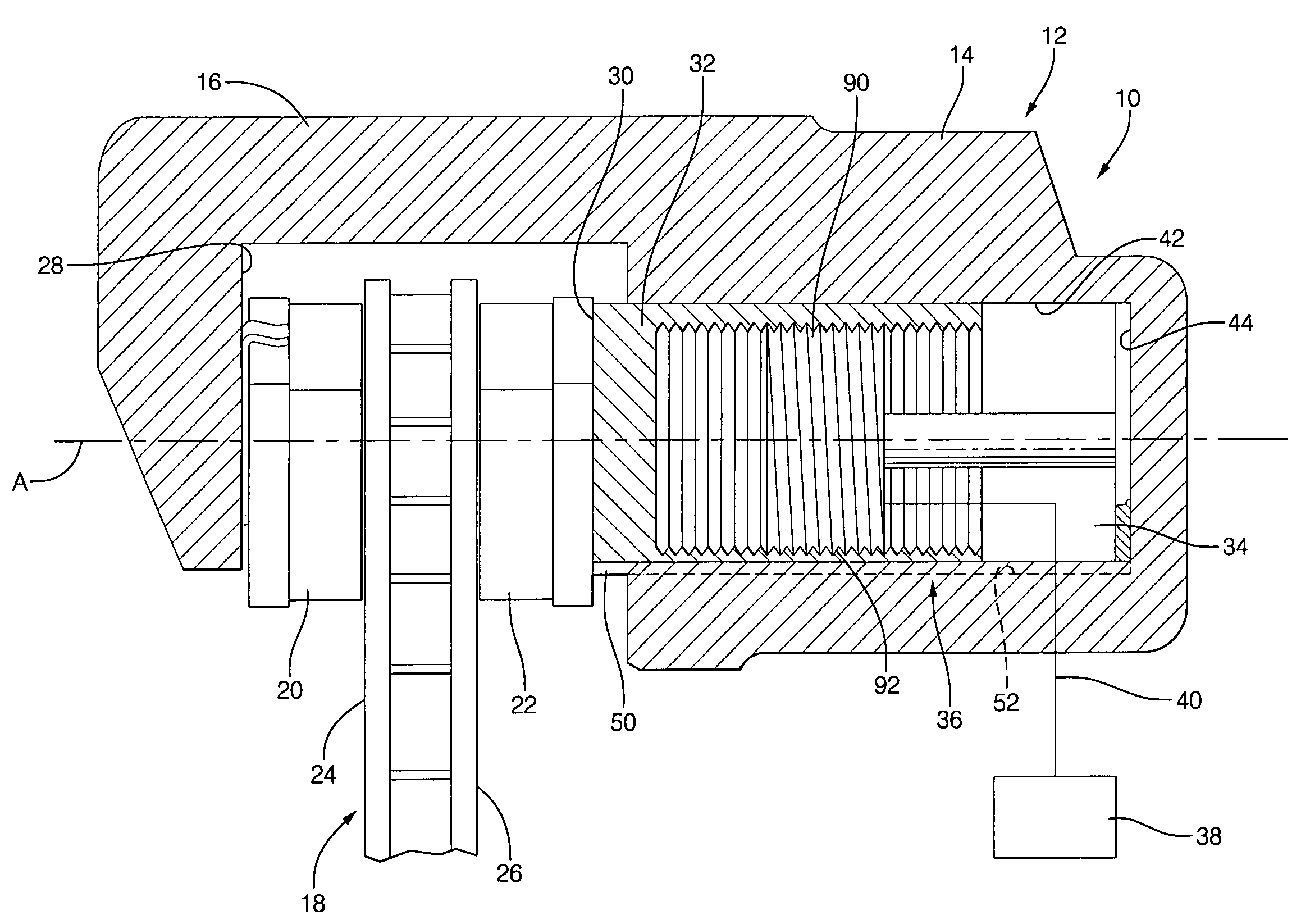
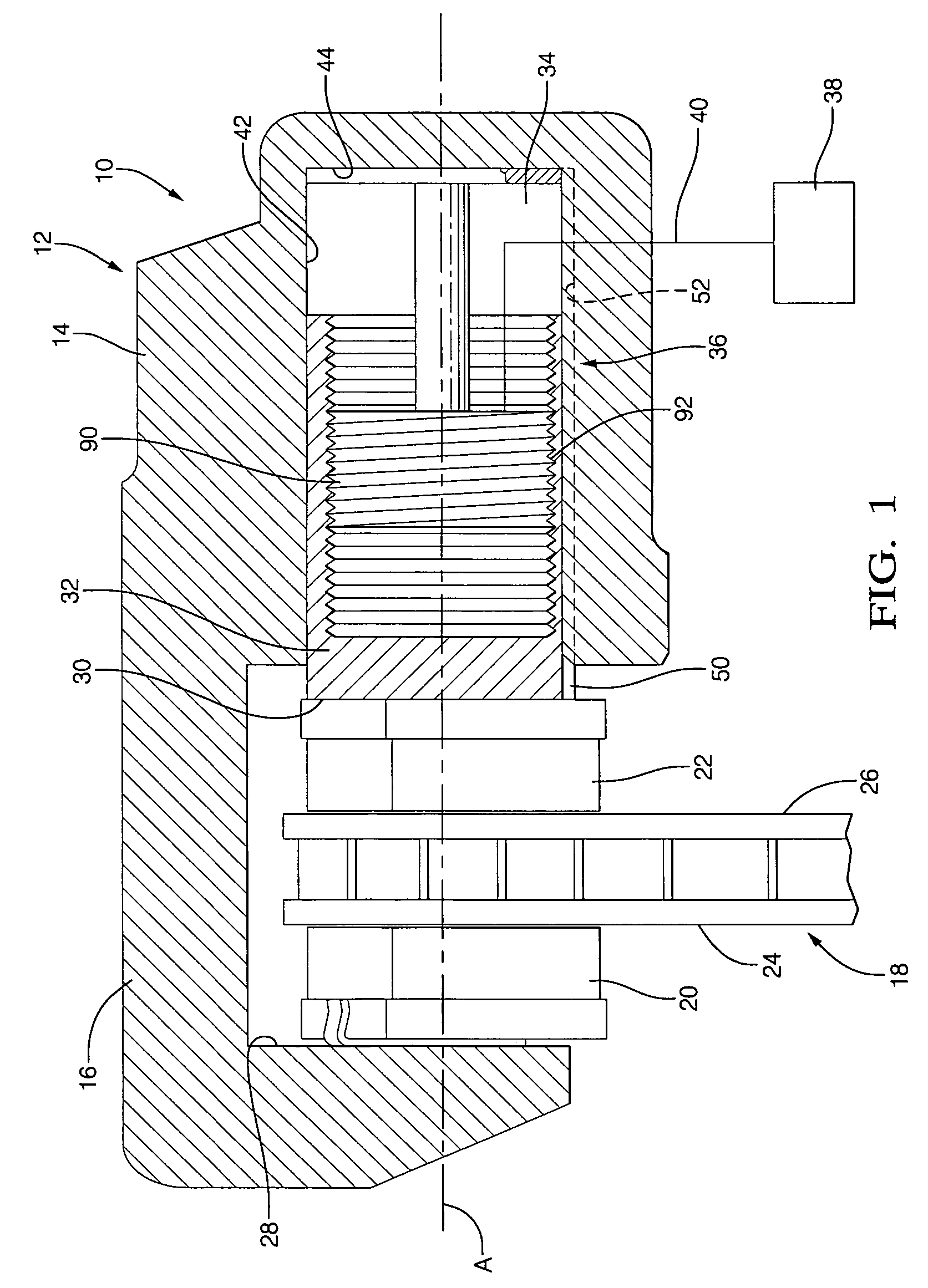
[0031]Referring to FIG. 1, a preferred environment and application of the present invention within the brake system of a passenger vehicle is illustrated. A brake caliper apparatus 10 may include mounting means (not illustrated) for grounding or securing the caliper apparatus 10 to the chassis of a motor vehicle in a manner well known in the art. The caliper apparatus 10 consists of a one-piece cast iron body 12 having an actuator housing portion 14 and an integral brake pad positioning / support portion 16. In application, the body 12 is disposed adjacent the radially outermost portions of...


PUM


Abstract

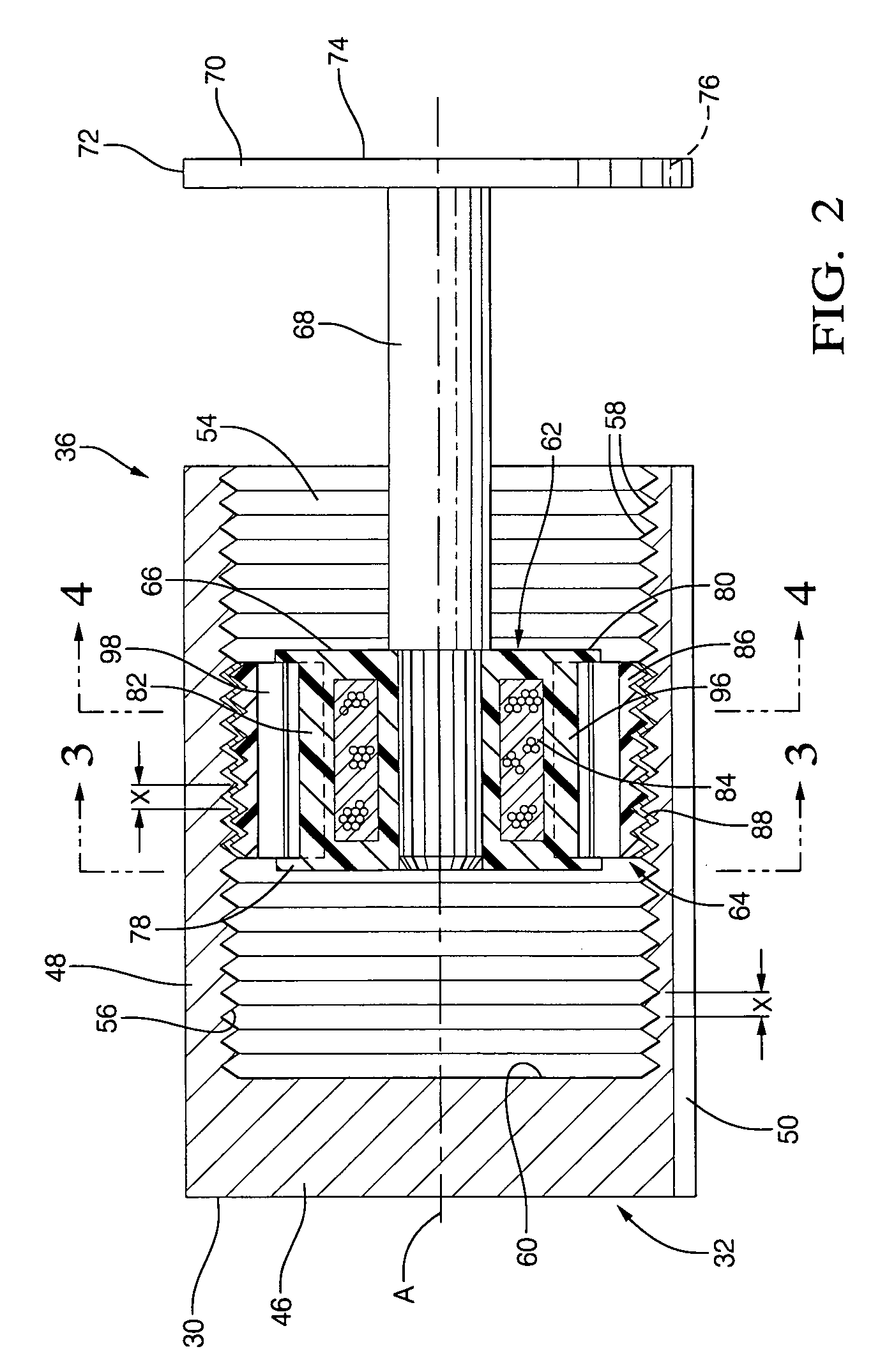
A harmonic drive linear actuator includes a first annular member defining a longitudinal axis and lying on a plane, which is perpendicular to the longitudinal axis. The first member is relatively flexible along a direction parallel to the plane. A second member is substantially coaxially aligned with the first member to define opposed substantially cylindrical surfaces and are fixed for non-relative rotation about the longitudinal axis. An actuator is provided for flexing the first annular member into at least two spaced-apart points of contact between the opposed surfaces and for sequentially flexing the first member to rotate the at least two points of contact circumferentially about the axis. The first and second surfaces define cooperating thread-forms thereon, which selectively engage to effect controlled, bidirectional relative axial displacement between the members in response to sequential flexure of the first member. The linear actuator can be conjoined with an actuator piston of a vehicle brake caliper assembly.

Description

RELATED PATENT APPLICATIONS[0001]This application claims priority to U.S. provisional patent applications Ser. No. 60 / 676,181 filed 29 Apr. 2005, entitled “Harmonic Linear Actuator” and Ser. No. 60 / 691,144 filed 16 Jun. 2005, entitled “Harmonic Linear Actuator and Flexing Splined Interlock for Harmonic Motor or Linear Actuator.”TECHNICAL FIELD[0002]The present invention relates to electro-mechanical actuators, and particularly to linear actuators. More particularly still, the present invention relates to the application of harmonic drives as linear actuators and the adaptation thereof for automotive applications.BACKGROUND OF THE INVENTION[0003]Harmonic drives have been used as motors and actuators in many electro-mechanical applications. One type of harmonic motor has a rotatable rotor and a surrounding non-rotatable stator. The rotor makes a single point of contact with the inner circumference of the stator. The single point of contact rotates around (i.e. rolls around) the inner ...

Claims


Application Information

Patent Timeline
Patent Type & Authority Patents(United States)
IPC IPC(8): F16D55/08
CPCF16D65/18F16H25/2409F16H49/001H02K7/06H02K7/116F16D2121/24Y10T74/2151F16H2049/008F16H2049/003
Inventor BAUDENDISTEL, THOMAS A.KLODE, HARALD
Owner BWI CO LTD SA
Learn More