Method for extracting H2S from sour gas

a technology of sour gas and h2s, which is applied in the field of extracting h2s from sour gas, can solve the problems of forming foam that can be detrimental to the proper operation of the process, and affecting the safety of the process

Active Publication Date: 2009-05-12
NAT TANK
View PDF19 Cites 8 Cited by
  • Summary
  • Abstract
  • Description
  • Claims
  • Application Information

AI Technical Summary

Benefits of technology

[0012]The heavier, liquid component from inlet centrifugal separator is fed to the inlet of a flash vessel that has a liquid level therein with a gas collection area above the liquid level. In the flash vessel liquid and gas components are allowed to separate with a liquid slurry discharge that feeds into a bioreactor. Gas from the inlet centrifugal separator passes into a counter current absorber in which H2S is absorbed out of the gas component, that is, the H2S containing gas flows upwardly in the absorber contacting downwardly flowing recycled liquid. From the absorber liquid solution flows through a pressure reduction valve to a flash vessel. Within the flash vessel the liquid and gas components are allowed to separate. As a consequence of the pressure reduction the separation process results in the creation of a heavy foam which passes with the gas components into the flash vessel. The gas component is passed into a tangential inlet of an intermediate centrifugal separator where high gas velocity produces a strong centrifugal separation force of about 150 G's. The whirling stream with its high G force collapses the foam and separates the liquid component of the inlet stream from the gas component and passes the liquid component downwardly within the centrifugal separator while the less heavy gas component migrates to the interior of the whirling stream to form a vortex that passes out through an axial gas outlet. The high G forces within intermediate centrifugal separator serve to effectively remove any foam component associated with the liquid stream, the bubbles of the foam collapsing under the high G forces to form gas that passes out through the outlet while the liquid component, having all foam extracted therefrom goes through a level control valve that serves to maintain a liquid level in the bottom portion of the intermediate centrifugal separator, and then the slurry merges with the slurry discharge from the flash vessel to flow into the bioreactor.
[0014]Thus the system of the invention provides a process for the removal of sulfur compounds, including specifically H2S. The system makes use of high gravitational separation forces available in a centrifugal separator to alleviate the problem that frequently arises from the tendency of an absorber to produce a foamy discharge in the process of H2S removal.

Problems solved by technology

Hydrogen sulfide gas has a number of undesirable properties.
Paradoxically, at concentrations greater than 100 parts per million (ppm), the gas can no longer be smelled, but it will induce dizziness.
Concentrations of greater than about 500 ppm can be fatal to humans.
An unfortunate side effect of most of these biological sulfur removal processes is formation of foam that can be detrimental to the proper operation of the process.
The formation of foam in the processing equipment can be caused by excessive sulfur solids concentration, flashing of dissolved gas during pressure reduction, counter current gas / solution flow, agitation, shear through spray nozzles and pumps, presence of surfactants and other causes.
Conventional separation devices are not effective in handling this type of foam.

Method used


Image

  • Method for extracting H2S from sour gas

Examples


Embodiment Construction

[0018]It is to be understood that the invention that is now to be described is not limited in its application to the details of the construction and arrangement of the parts illustrated in the accompanying drawings. The invention is capable of other embodiments and of being practiced or carried out in a variety of ways. The phraseology and terminology employed herein are for purposes of description and not limitation.

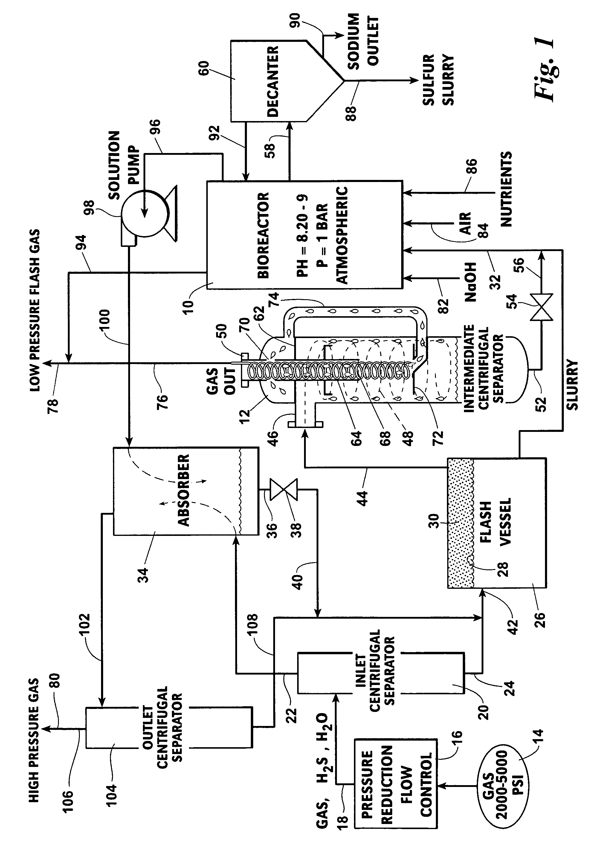
[0019]Elements shown by the drawings are identified by the following numbers:

[0020]

10Bioreactor12Intermediate centrifugal separator14Gas source16Pressure reduction flow control18Conduit20Inlet centrifugal separator22Gas outlet piping24Liquid outlet piping26Flash vessel28Liquid level30Gas collection area32Liquid slurry discharge34Counter current absorber36Liquid outlet38Pressure reduction valve40Conduit42Liquid inlet44Gas conduit46Inlet48Swirling stream50Gas outlet52Liquid outlet54Level control valve56Conduit58Inlet60Decanter62Baffle64Vortex finder68Vortex70Circumferenti...


PUM

PropertyMeasurementUnit
sizeaaaaaaaaaa
gravitational forceaaaaaaaaaa
alkalineaaaaaaaaaa

Abstract

This invention teaches a process that includes extraction of gas in which the presence of foam results in the carry over in the outlet gas stream of excessive liquids and / or solids, including the steps of injecting the foam laden gas stream tangentially into a cyclonic separator having an axial gas outlet and a liquid outlet, under conditions in which the inlet stream is subjected to at least about 150 G's, the outlet gas being substantially liquids / solids free and the outlet liquid stream being conveyed for disposal or further processing.

Description

REFERENCE TO PENDING APPLICATIONS[0001]This application is not based upon any pending domestic or international patent applications.FIELD OF THE INVENTION[0002]This invention relates to a process for the removal of sulfur compounds from a gas flow stream that is treated in a bioreactor and an absorber, the output of the absorber is fed into a centrifugal separator for separation of gas and foam, the residue of which is fed to a decanter providing a sulfur slurry from which elemental sulfur may be obtained, the resultant gas stream being substantially free of sulfur.BACKGROUND OF THE INVENTION[0003]Hydrogen sulfide gas has a number of undesirable properties. At low concentrations (i.e., less than 10 parts per million), the gas has a strong odor of “rotten eggs”. Paradoxically, at concentrations greater than 100 parts per million (ppm), the gas can no longer be smelled, but it will induce dizziness. Concentrations of greater than about 500 ppm can be fatal to humans. Hydrogen sulfide ...

Claims


Application Information

Patent Timeline
Patent Type & Authority Patents(United States)
IPC IPC(8): B01D19/00B01D19/02C01B17/05C10L3/10C12P3/00
CPCC10L3/10C10L3/102Y10S423/17B01D53/52C10G17/00C10G45/00
Inventor LANNING, ROBERT A.BRUSSO, F. STEPHENSAMS, GARY W.
Owner NAT TANK
Why Eureka
Try Eureka