

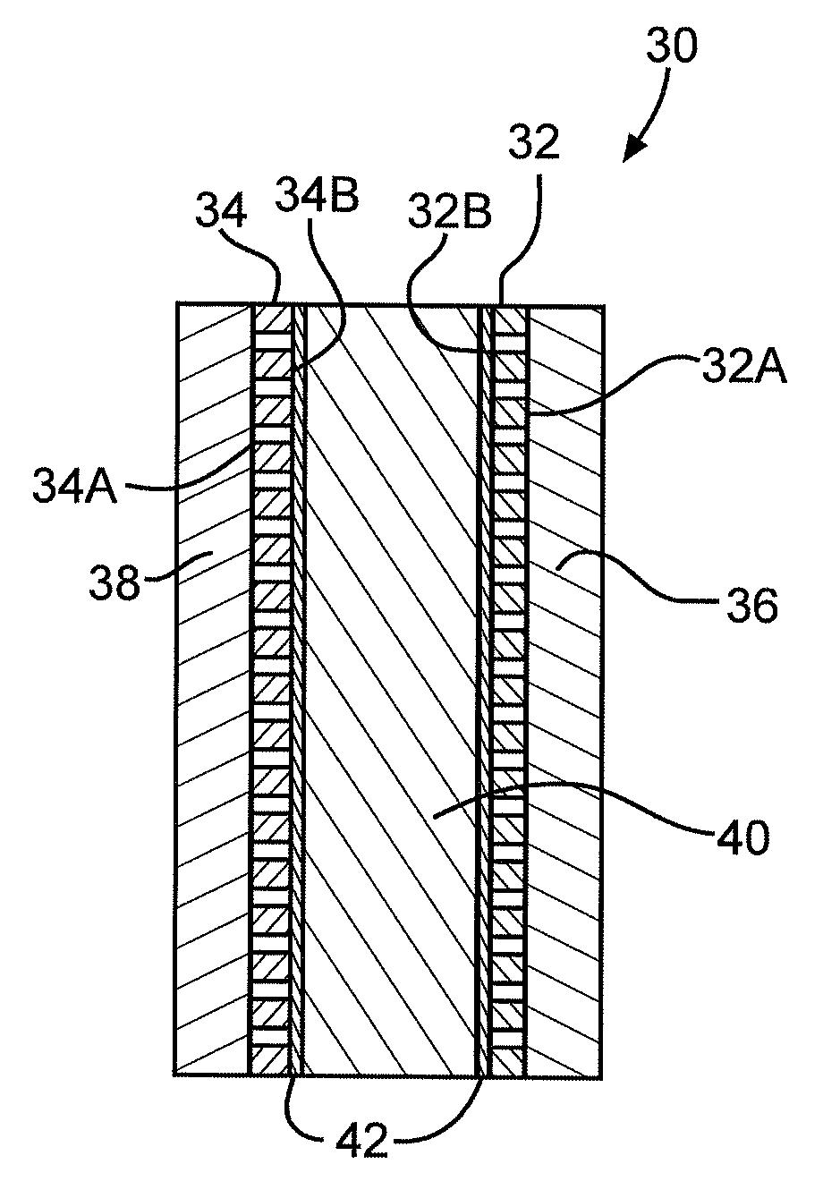
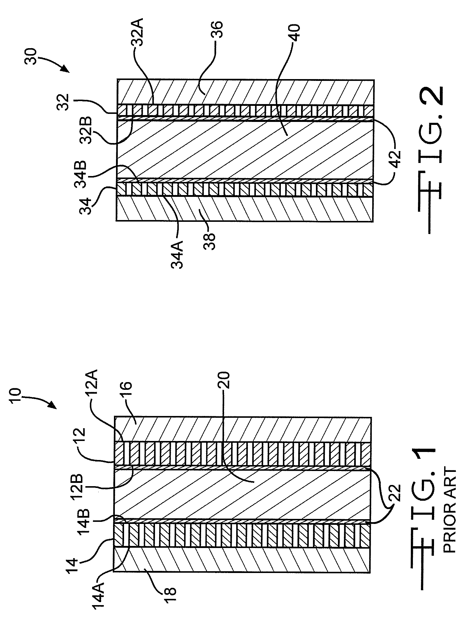
Sandwich electrode design having relatively thin current collectors
a current collector and electrode design technology, applied in the direction of positive electrodes, electrochemical generators, cell components, etc., can solve the problems of svo material potential dropping due to capacity loss, and cannot be used in medical devices requiring a high rate discharge application, etc., to achieve high rate capability, improve the performance of lithium sandwich cathode electrochemical cells, and improve the effect of electrochemical cell performan
- Summary
- Abstract
- Description
- Claims
- Application Information
AI Technical Summary
Benefits of technology
Problems solved by technology
Method used
Image

Examples
Embodiment Construction
[0016]As used herein, the term “pulse” means a short burst of electrical current of significantly greater amplitude than that of a pre-pulse current immediately prior to the pulse. A pulse train consists of at least two pulses of electrical current delivered in relatively short succession with or without open circuit rest between the pulses. An exemplary pulse train may consist of four 10-second pulses (23.2 m / cm2) with a 15 second rest between each pulse. A typically used range of current densities for cells powering implantable medical devices is from about 15 mA / cm2 to about 50 mA / cm2, and more preferably from about 18 mA / cm2 to about 35 mA / cm2. Typically, a 10 second pulse is suitable for medical implantable applications. However, it could be significantly shorter or longer depending on the specific cell design and chemistry.
[0017]An electrochemical cell that possesses sufficient energy density and discharge capacity required to meet the vigorous requirements of implantable medi...
PUM
| Property | Measurement | Unit |
|---|---|---|
| thickness | aaaaa | aaaaa |
| thick | aaaaa | aaaaa |
| current densities | aaaaa | aaaaa |
Abstract
Description
Claims
Application Information