
Interrogating multi-featured arrays

a multi-featured array and array technology, applied in the field of arrays, can solve the problems of difficult to reliably switch between two power levels quickly, low dna quantity available for arrays, and high cost, and achieve the effect of rapid alteration of interrogating light power, simple apparatus, and fast change of power level

Inactive Publication Date: 2009-05-12
AGILENT TECH INC
View PDF9 Cites 49 Cited by
  • Summary
  • Abstract
  • Description
  • Claims
  • Application Information

AI Technical Summary

Benefits of technology

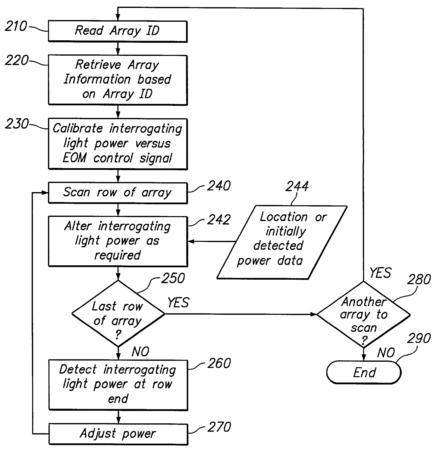
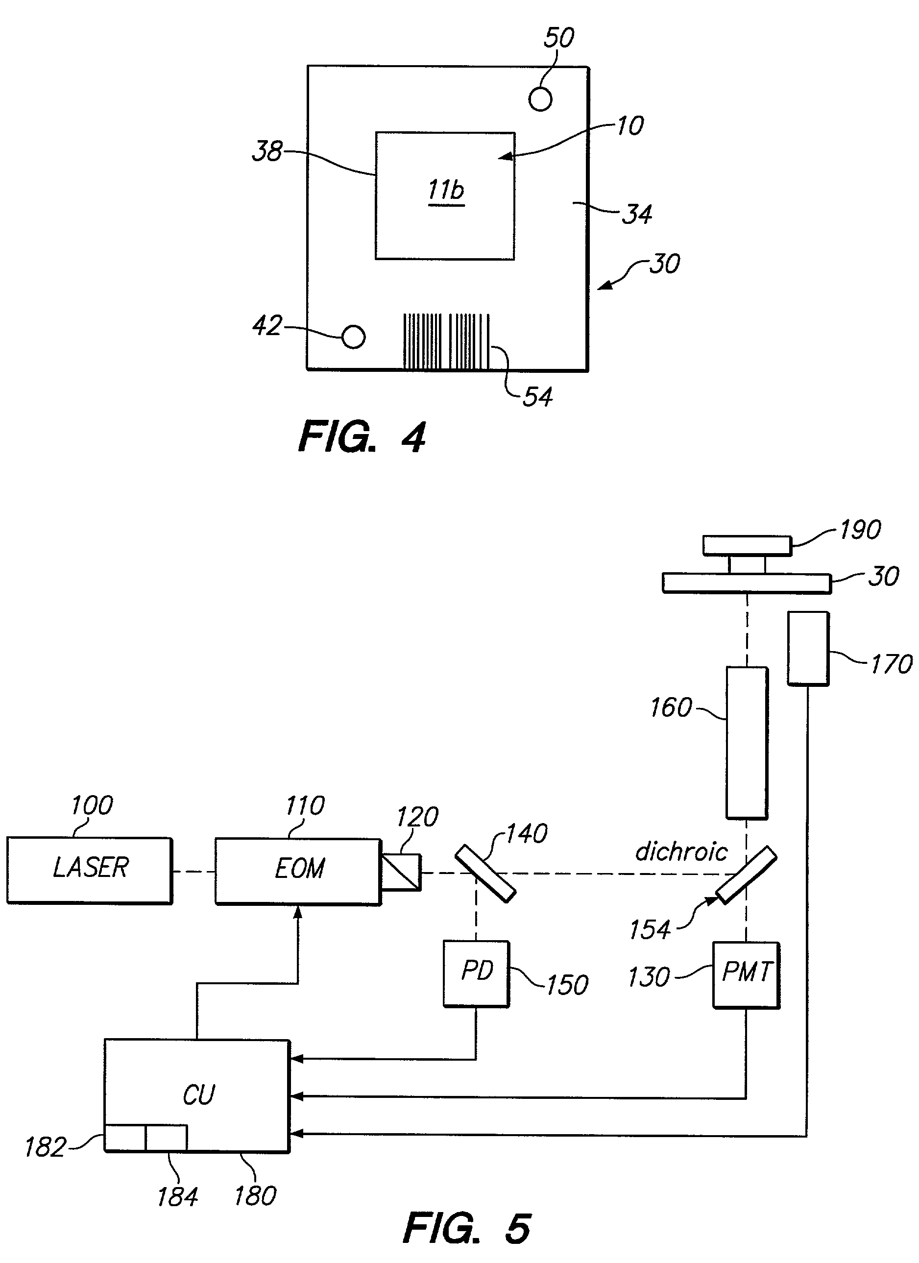
The present invention provides a method for detecting multiple features on an array of different moieties using an interrogating light. The interrogating light is scanned across the array and emitted signals from the features are detected. The power of the interrogating light is adjusted based on the detected signals and the location of the features. The method can be executed using an apparatus that includes a light source, variable optical attenuator, scanning system, emitted signal detector, and power detector. The apparatus can also include a reader to machine read an identification carried on the array package. The technical effects of the invention include improved accuracy and sensitivity in detecting multiple features on an array and improved efficiency in adjusting the interrogating light power based on the detected signals.

Problems solved by technology

In array fabrication, the quantities of DNA available for the array are usually very small and expensive.
Laser output power in such array scanners may tend to drift over time.
However, the present invention recognizes that for some types of gas lasers it may be difficult to reliably switch between two power levels quickly, and that for diode lasers changing the laser power may have the undesired side effect of changing the wavelength.
In PMTs and other detectors (such as CCDs) very strong signals that are (depending on the type of detector) either spatially and / or temporally close to weak signals, may undesirably affect the latter.
Extremely strong signals may even damage either kind of (normally expensive) detector.
In any event, the accurate detection of signals from an array being interrogated by the scanner may be in doubt due to such effects.

Method used


Image

  • Interrogating multi-featured arrays
  • Interrogating multi-featured arrays
  • Interrogating multi-featured arrays

Examples


Embodiment Construction

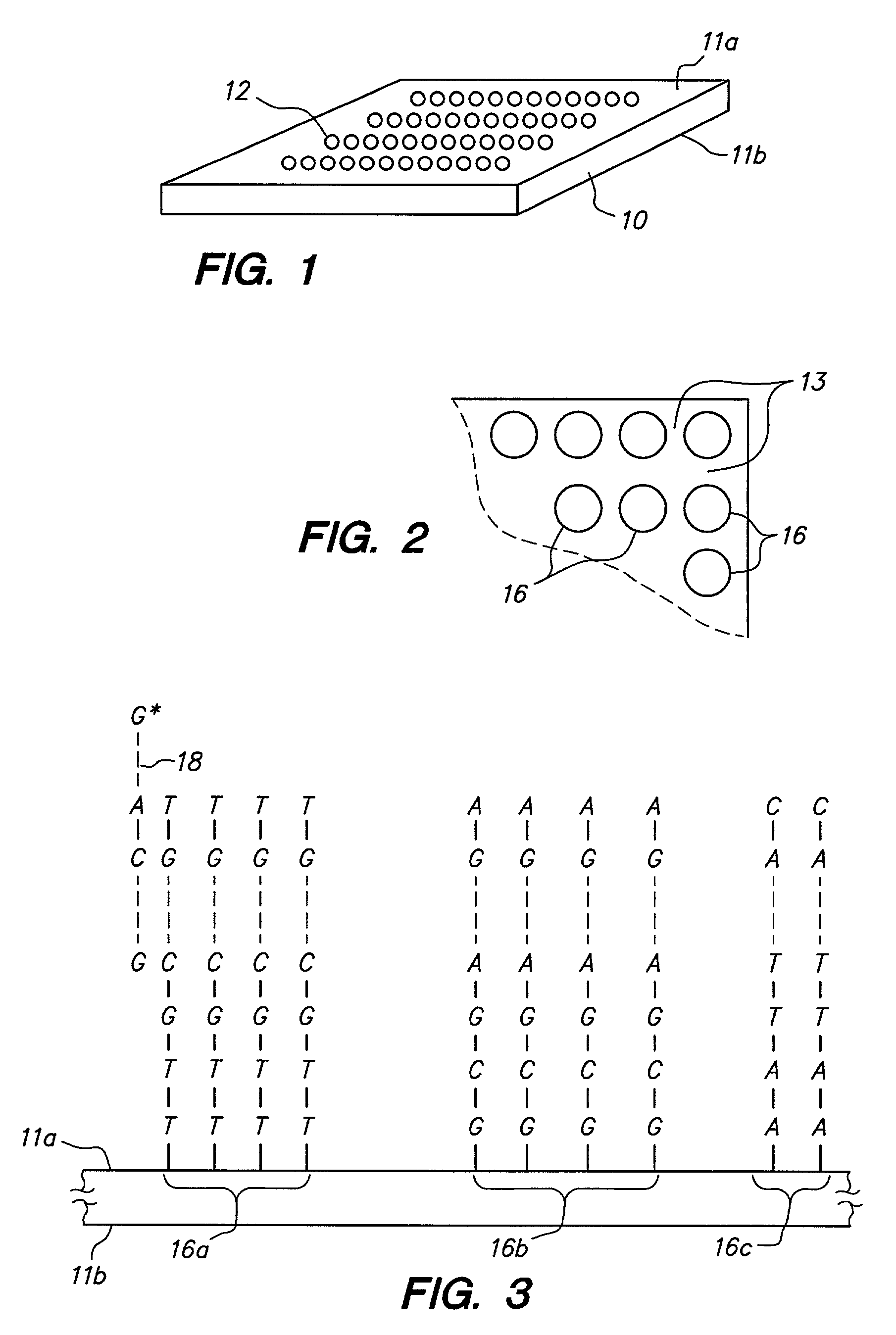
[0027]Throughout the present application, unless a contrary intention appears, the following terms refer to the indicated characteristics. A “biopolymer” is a polymer of one or more types of repeating units. Biopolymers are typically found in biological systems and particularly include peptides or polynucleotides, as well as such compounds composed of or containing amino acid or nucleotide analogs or non-nucleotide groups. This includes polynucleotides in which the conventional backbone has been replaced with a non-naturally occurring or synthetic backbone, and nucleic acids (or synthetic or naturally occurring analogs) in which one or more of the conventional bases has been replaced with a group (natural or synthetic) capable of participating in Watson-Crick type hydrogen bonding interactions. Polynucleotides include single or multiple stranded configurations, where one or more of the strands may or may not be completely aligned with another. A “nucleotide” refers to a sub-unit of ...


PUM

PropertyMeasurementUnit
thicknessaaaaaaaaaa
thicknessaaaaaaaaaa
thicknessaaaaaaaaaa

Abstract

A method, apparatus for executing the method, and computer program products for use in such an apparatus. The method includes scanning an interrogating light across multiple sites on an array package including an addressable array of multiple features of different moieties, which scanned sites include multiple array features. Signals from respective scanned sites emitted in response to the interrogating light are detected. The interrogating light power is altered for a first site on the array package during the array scan, based on location of the first site or on a determination that the emitted signal from the first site will be outside a predetermined value absent the altering (which allows for protecting a detector against expected overly bright sites), or is altered during the array scan based on the detected interrogating light power (which allows for compensating for light source drift during an array scan).

Description

CROSS REFERENCE TO RELATED APPLICATION(S)[0001]This is a continuation of application Ser. No. 09 / 430,214 filed on Oct. 29, 1999 now U.S. Pat. No. 6,406,849.FIELD OF THE INVENTION[0002]This invention relates to arrays, particularly biopolymer arrays such as DNA arrays, which are useful in diagnostic, screening, gene expression analysis, and other applications.BACKGROUND OF THE INVENTION[0003]Polynucleotide arrays (such as DNA or RNA arrays), are known and are used, for example, as diagnostic or screening tools. Such arrays include features (sometimes referenced as spots or regions) of usually different sequence polynucleotides arranged in a predetermined configuration on a substrate. The array is “addressable” in that different features have different predetermined locations (“addresses”) on a substrate carrying the array.[0004]Biopolymer arrays can be fabricated using in situ synthesis methods or deposition of the previously obtained biopolymers. The in situ synthesis methods includ...

Claims


Application Information

Patent Timeline
Patent Type & Authority Patents(United States)
IPC IPC(8): C12Q1/68C12M1/00G01N15/06C12M1/36G01N21/25G01N21/27G01N21/64G06T5/00
CPCG01N21/274G01N21/6452G01N21/6428G01N2201/1242
Inventor DORSEL, ANDREAS N.SCHLEIFER, KYLE J.WHITE, ELECIA C.LADD, CHARLES S.SILLMAN, DEBRA A.
Owner AGILENT TECH INC
Learn More