
Apparatus and method for supplying DC power source

a technology of dc power supply and apparatus, which is applied in the direction of converting intermediate to dc, efficient power electronics conversion, building scaffolds, etc., can solve the problems of increasing the fabricating cost of the apparatus for supplying the dc power source according to the related art, and the difficulty of satisfying the pfc spec, so as to achieve the effect of decreasing the fabricating cos

Inactive Publication Date: 2009-05-12
LG ELECTRONICS INC
View PDF12 Cites 18 Cited by
  • Summary
  • Abstract
  • Description
  • Claims
  • Application Information

AI Technical Summary

Benefits of technology

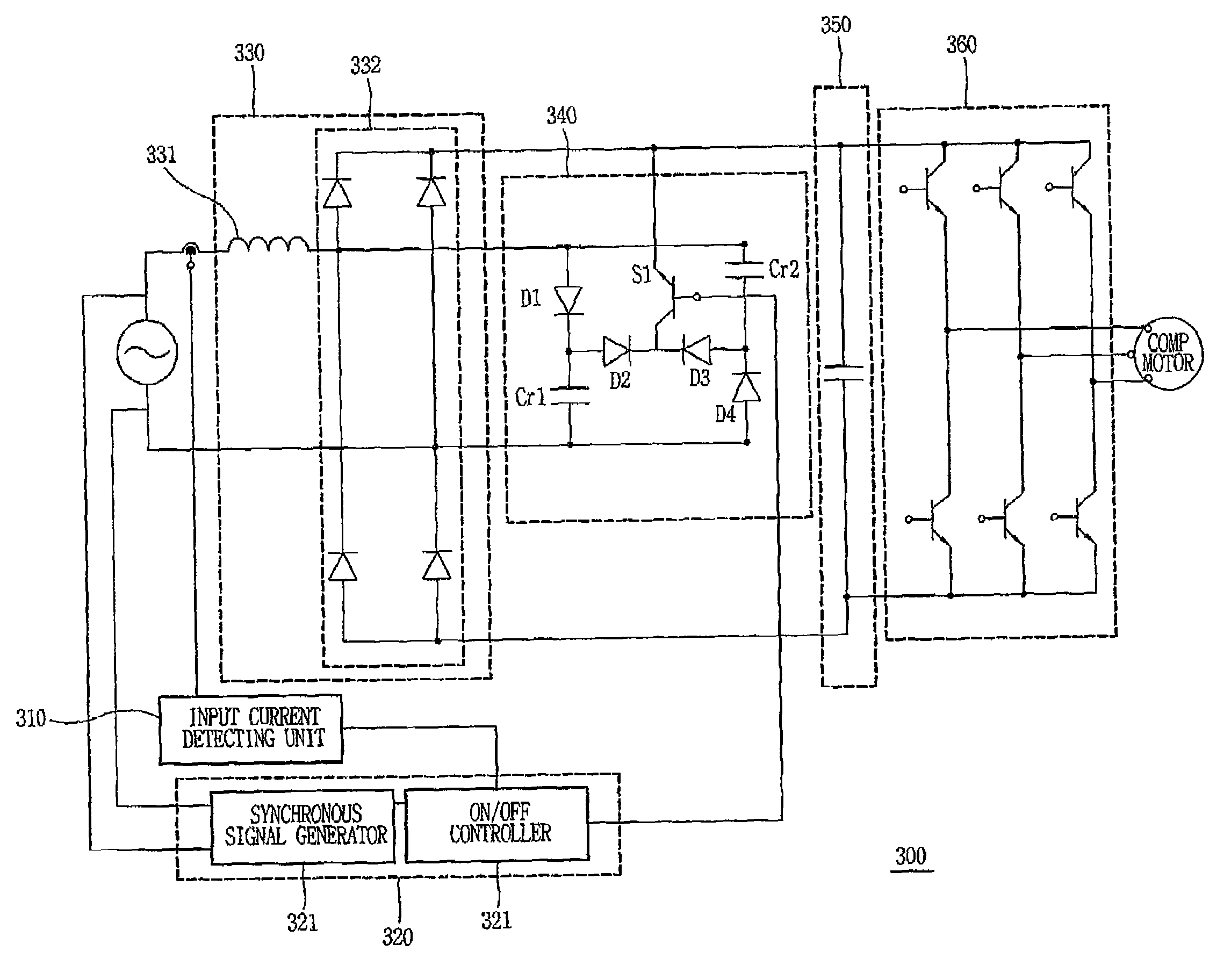
[0019]Therefore, an object of the present invention is to provide an apparatus and method for supplying a direct power source supply which is capable of compensating a power factor of an input power source by detecting an input current amount according to load changes to determine a load size, controlling the power factor based upon the determined load size, and varying a current amount supplied to the load, and which is also capable of decreasing a fabricating cost by using a reactor with a low capacity.

Problems solved by technology

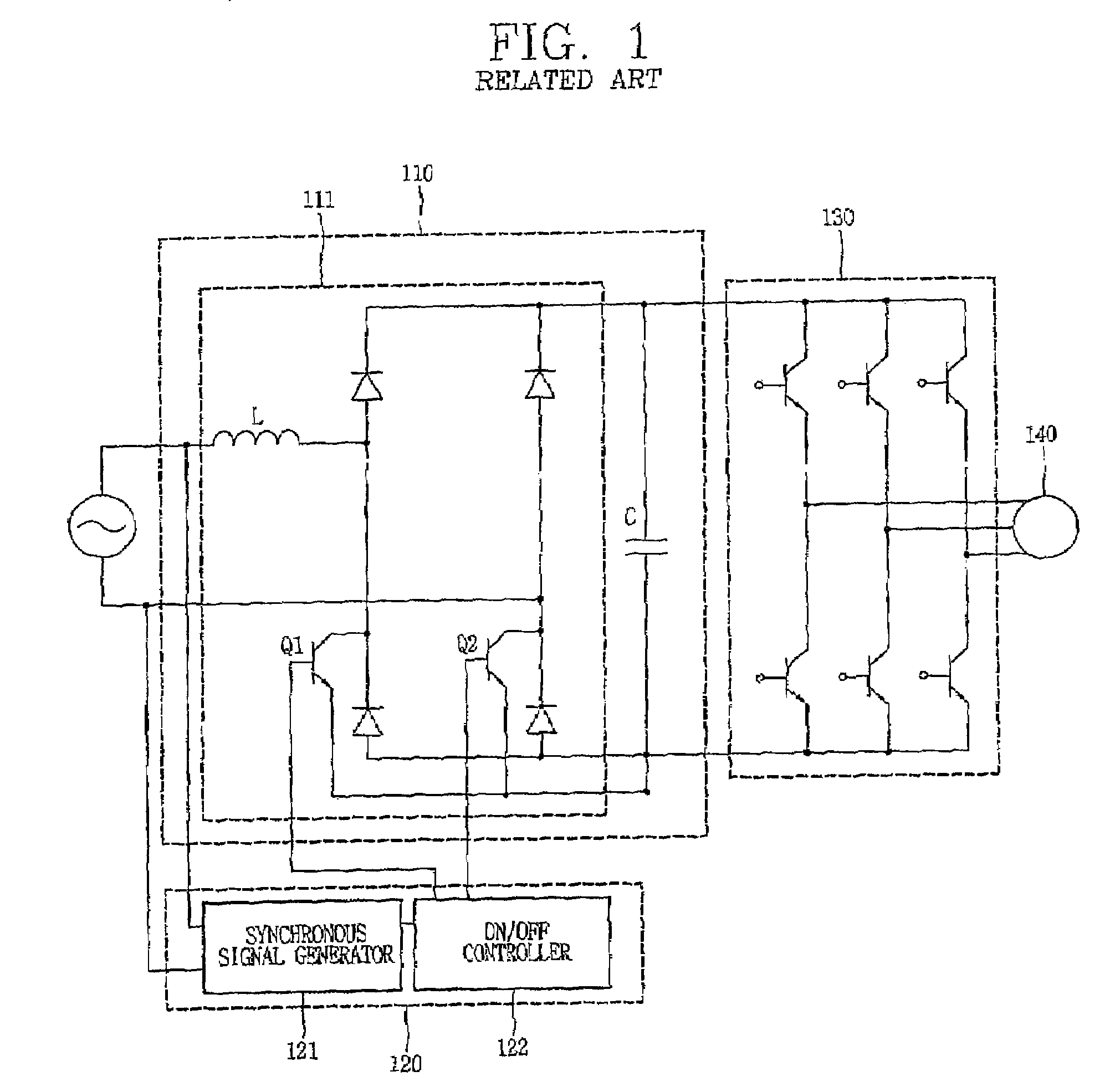
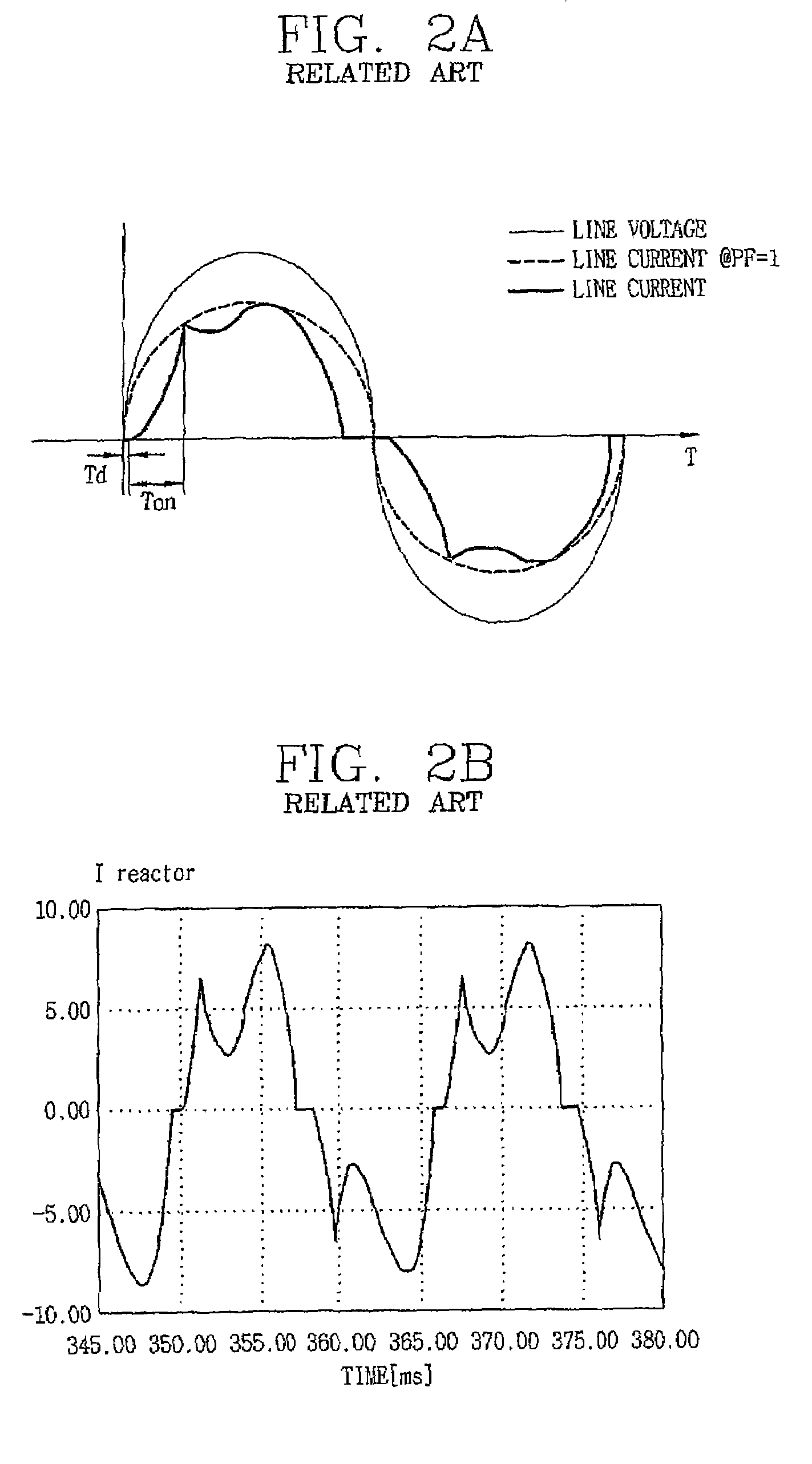
However, the apparatus for supplying the DC power source according to the related art drove the active filter 300 without considering the load changes, in case of a high load, it was difficult to satisfy the PFC spec.
Furthermore, in case of a low load, the apparatus for supplying the DC power source according to the related art occurred energy loss at the power semiconductor device due to the PFC operation.
In addition, the apparatus for supplying the DC power source according to the related art increased a fabricating cost due to using the reactor L with a great capacity for the harmonic removal and the PFC.

Method used


Image

  • Apparatus and method for supplying DC power source
  • Apparatus and method for supplying DC power source
  • Apparatus and method for supplying DC power source

Examples


Embodiment Construction

[0032]Description will now be given in detail of the present invention, with reference to the accompanying drawings.

[0033]Preferred embodiments of an apparatus and method for supplying a DC power source according to the present invention will now be explained in detail with reference to FIGS. 3 through 5 hereafter.

[0034]As shown in FIG. 3, an apparatus 300 for supplying a DC power source comprises an input current detecting unit 310 for detecting an input current amount to determine and output a load size, a switching control unit 320 for outputting a switching control signal to compensate a power factor of an input power source based upon the determined load size, a filtering / rectifying unit 330 for reducing a harmonic of the input current and rectifying an input alternating current (AC) voltage, a power factor compensating unit 340 for supplying charged energy based upon the switching control signal, a smoothing unit 350 for smoothing the rectified input AC voltage into a DC volta...


PUM


Abstract

An apparatus and method for supplying a direct current power source capable of compensating a power factor of an input power source by increasing and decreasing energy required by load changes, the apparatus comprising: an input current detecting unit for detecting an input current amount to determine a load size, a switching control unit for outputting a switching control signal to compensate a power factor of an input power source based upon the determined load size, a filtering / rectifying unit for reducing a harmonic of the input current and rectifying an input AC voltage, a power factor compensating unit for supplying charged energy to the load based upon the switching control signal, a smoothing unit for smoothing the rectified input AC voltage into a DC voltage, and an inverter for converting the smoothed DC voltage into an AC voltage and outputting the converted AC voltage to drive the load, whereby the power factor compensation (PFC) standard can be satisfied although the load is increased, and a fabricating cost can be reduced by using a reactor with a low capacity.

Description

RELATED APPLICATION[0001]The present disclosure relates to subject matter contained in priority Korean Application No. 10-2006-0023713, filed on Mar. 14, 2006, which is herein expressly incorporated by reference in its entirety.BACKGROUND OF THE INVENTION[0002]1. Field of the Invention[0003]The present invention relates to an apparatus and method for supplying a power source, and particularly, to an apparatus and method for supplying a DC power source for driving a compressor of an air conditioner.[0004]2. Background of the Invention[0005]Air conditioners are currently using a three-phase motor as a driving motor of a compressor. A power source supply apparatus of the three-phase motor converts Alternating Current (AC) of a commercial power source into Direct Current (DC), and thereafter re-converts the converted DC into the AC using an inverter. The re-converted AC is then applied to the three-phase motor to drive it.[0006]An apparatus for supplying a DC power source according to t...

Claims


Application Information

Patent Timeline
Patent Type & Authority Patents(United States)
IPC IPC(8): H02M5/40
CPCH02M1/4208H02M2001/007Y02B70/126Y02B70/10H02M1/007H02M1/0085E04G7/22E04G7/32E04G21/3204
Inventor LIM, SUN-KYOUNGKIM, DAI-HYUNKIM, HAG-WONE
Owner LG ELECTRONICS INC
Learn More