Implantable medical apparatus having an omnidirectional antenna for receiving radio frequency signals

a radio frequency signal and implantable technology, applied in the field of medical devices, can solve the problems of not always being able to optimally orient the antenna for maximum energy reception, and the electromagnetic field of the rf signal is not always properly aligned with the antenna of the implanted device, so as to improve the reception of radio frequency signals and increase strength

Inactive Publication Date: 2009-05-12
KENERGY INC
View PDF16 Cites 87 Cited by
  • Summary
  • Abstract
  • Description
  • Claims
  • Application Information

AI Technical Summary

Benefits of technology

[0015]The various versions of the present antenna assembly provide multiple antennas each for receiving the radio frequency signal that propagates along a given axis. This enhances reception of the radio frequency signal regardless of the orientation of the medical device to the propagation axis. In other cases, the radio frequency signal has a plurality of components, each propagating along a different axis and each antenna of the assembly receives a different one of those component. The individual electrical signals produced in each antenna are additively combined into a single signal having greater strength than each of the individual electrical signals.

Problems solved by technology

One of the difficulties in such a wireless system is ensuring that the radio frequency signal and a maximum amount of the RF energy is received by the stimulator device.
However, since the antenna can be implanted in different orientations in the patient's body depending on the location of the vein or artery and the orientation of the transmitter antenna similarly varies, it is difficult to ensure that the electromagnetic field from the RF signal will be properly aligned with the antenna of the implanted device.
Because choosing the location at which the medical device in implanted is based primarily on cardiac stimulation criteria, it is not always possible to optimally orient its antenna for maximum energy reception.
Although this solves the problem of misalignment of the transmitter and receiver antennas, the RF energy from all the electromagnetic waves is not received by the implanted device.

Method used


Image

  • Implantable medical apparatus having an omnidirectional antenna for receiving radio frequency signals
  • Implantable medical apparatus having an omnidirectional antenna for receiving radio frequency signals
  • Implantable medical apparatus having an omnidirectional antenna for receiving radio frequency signals

Examples


Embodiment Construction

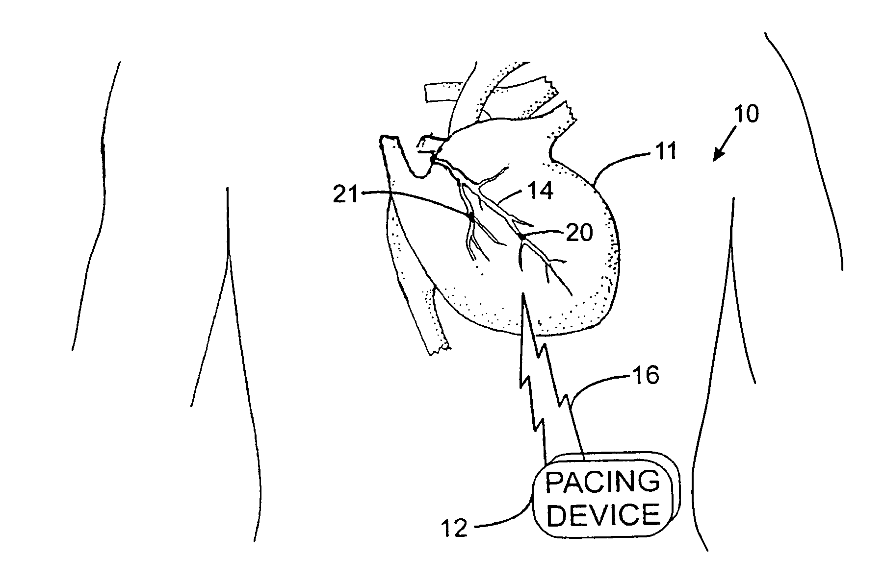
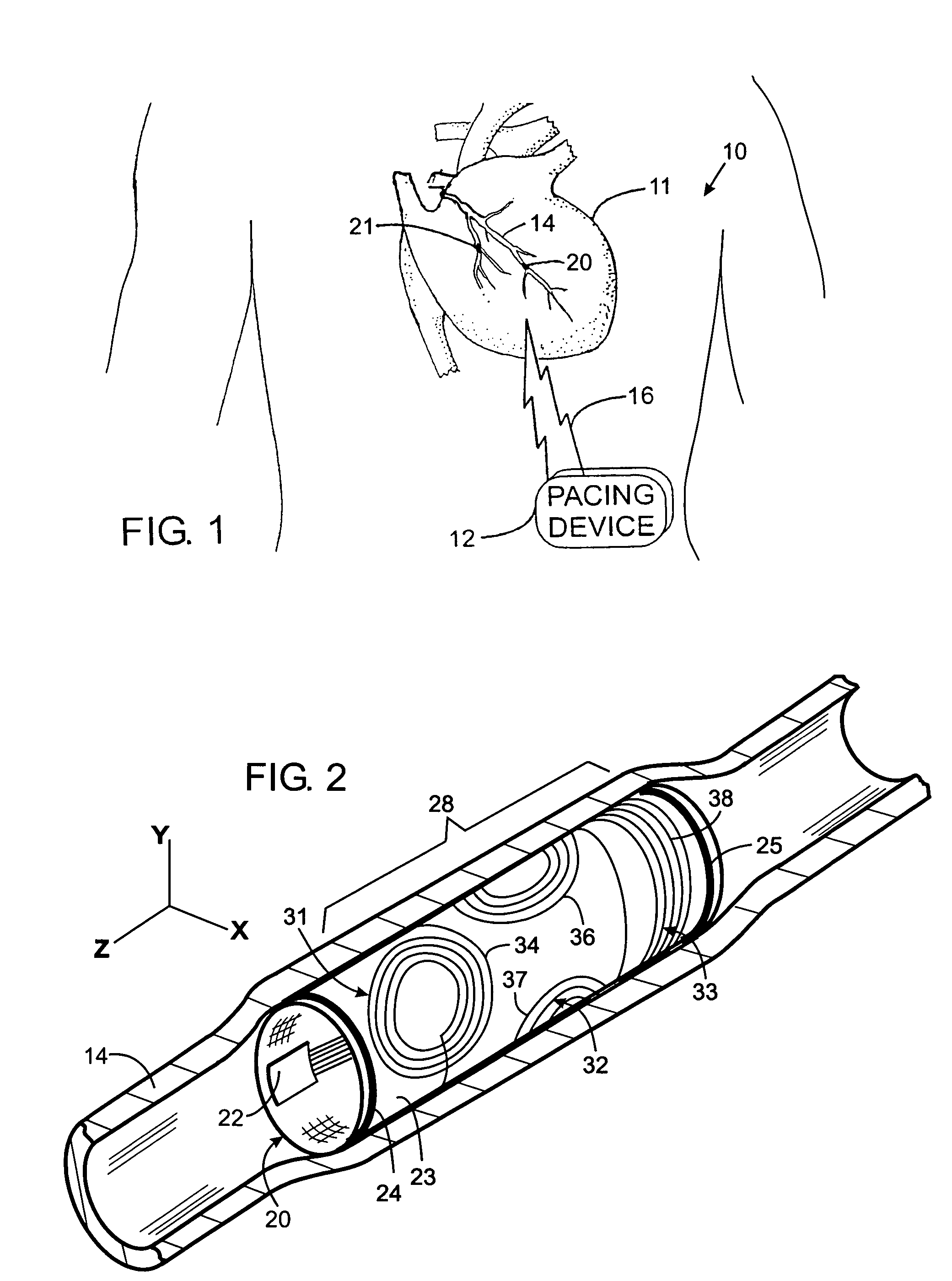
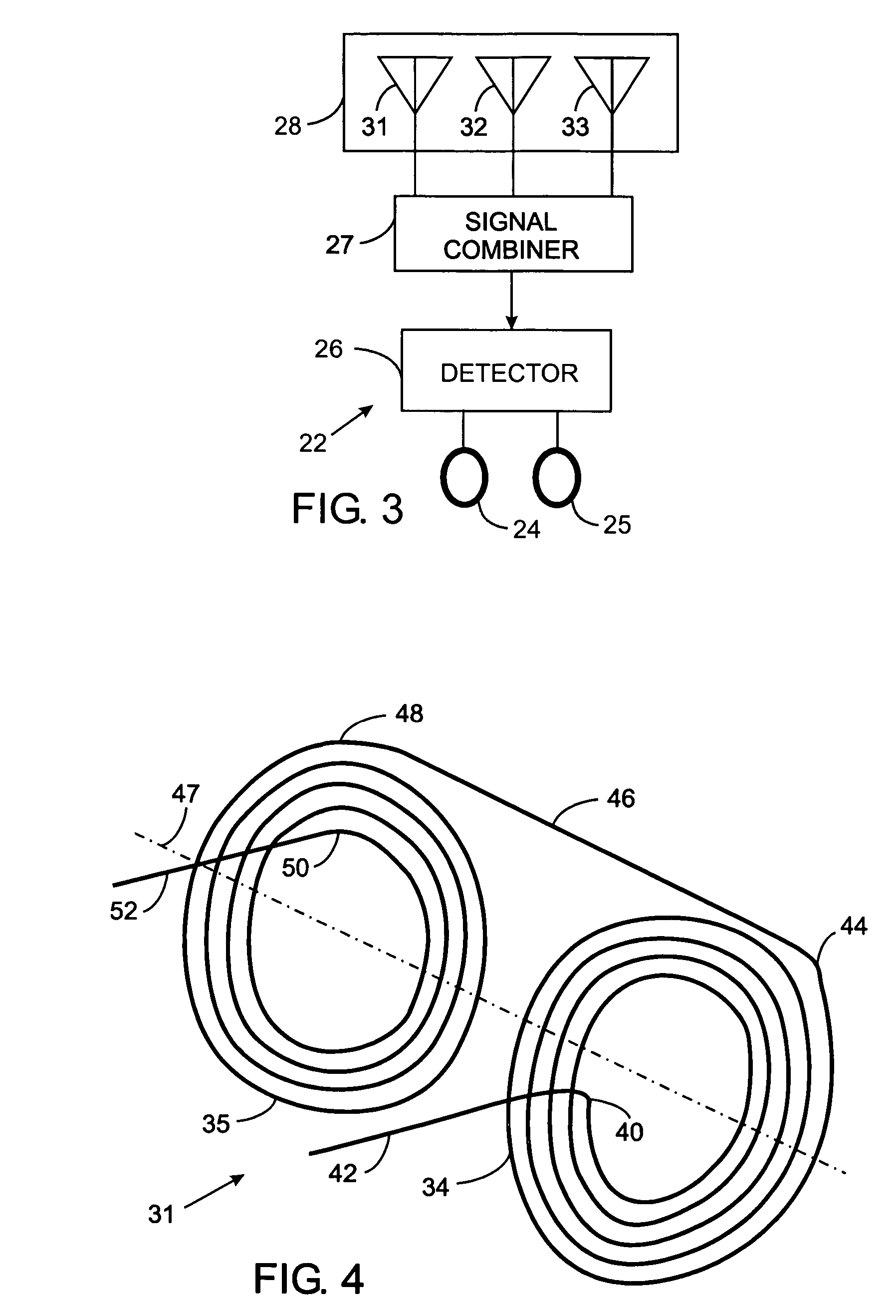
[0020]With initial reference to FIG. 1, an apparatus 10 for applying electrical stimulation to a heart 11 comprises a pacing device 12 and one or more stimulators 20 and 21 located in arteries or veins 14 through which blood flows within the heart muscles. As will be described in greater detail, the pacing device 12 emits a radio frequency signal 16 which produces an electric current in the implanted vascular stimulators, thereby stimulating the heart muscle to contract. The radio frequency signal 16 preferably comprises a set of electromagnetic waves the propagate along three orthogonal axes, however that signal alternatively may comprise a single electromagnetic wave or other pluralities of waves. Although the present invention is being described in the context of an apparatus for pacing the heart, the novel antenna system can be used with defibrillators and other implantable medical devices.

[0021]Referring to FIG. 2, a stimulator 20 is placed in the artery or vein 14 of the heart...


PUM


Abstract

An radio frequency antenna assembly is provided for a medical device such as one capable of being implanted into a patient. The antenna assembly includes a plurality of antennas, each oriented to receive a radio frequency signal propagating along a different axis. This facilitates reception of the radio frequency signal regardless of the orientation of its propagation axis to the medical device. In other cases, the radio frequency signal has a plurality of components, each propagating along a different axis, and each antenna of the assembly receives a different one of those components. The individual electrical signals produced in each antenna are additively combined into a single signal having greater strength than each of the individual electrical signals.

Description

CROSS-REFERENCE TO RELATED APPLICATIONS[0001]Not ApplicableSTATEMENT REGARDING FEDERALLY SPONSORED RESEARCH OR DEVELOPMENT[0002]Not ApplicableBACKGROUND OF THE INVENTION[0003]1. Field of the Invention[0004]The present invention relates to medical devices for implanting into an animal, such as cardiac stimulation devices, and more particularly to such medical devices that receive radio frequency signals via an antenna.[0005]2. Description of the Related Art[0006]A remedy for people with slowed or disrupted natural heart beats is to implant a cardiac pacing device which is a small electronic apparatus that stimulates the heart to beat at regular intervals. That device consists of a pulse generator, implanted in the patient's chest, which produces electrical pulses that stimulate heart contractions. Electrical wires extend from the pulse generator to several electrodes placed nearby specific muscles of the heart, which when electrically stimulated produce contraction of the adjacent he...

Claims


Application Information

Patent Timeline
Patent Type & Authority Patents(United States)
IPC IPC(8): A61N1/00
CPCA61N1/37229A61N1/3787H01Q7/00H01Q21/24A61F2/82A61F2250/0001Y10S128/903
Inventor DENKER, STEPHENBEUTLER, ARTHUR J.
Owner KENERGY INC
Why Eureka
Try Eureka