
Device for examining rotor drilled holes

a technology for rotor drilling and examining devices, which is applied in the direction of borehole/well accessories, instruments, surveys, etc., can solve the problems of inability to store observation and a true spatial representation, and the methods and apparatuses disclosed in these publications are not suitable for inspecting anchors

Active Publication Date: 2009-05-19
DEUTSCHE MONTAN TECHNOLOGIES GMBH
View PDF3 Cites 7 Cited by
  • Summary
  • Abstract
  • Description
  • Claims
  • Application Information

AI Technical Summary

Benefits of technology

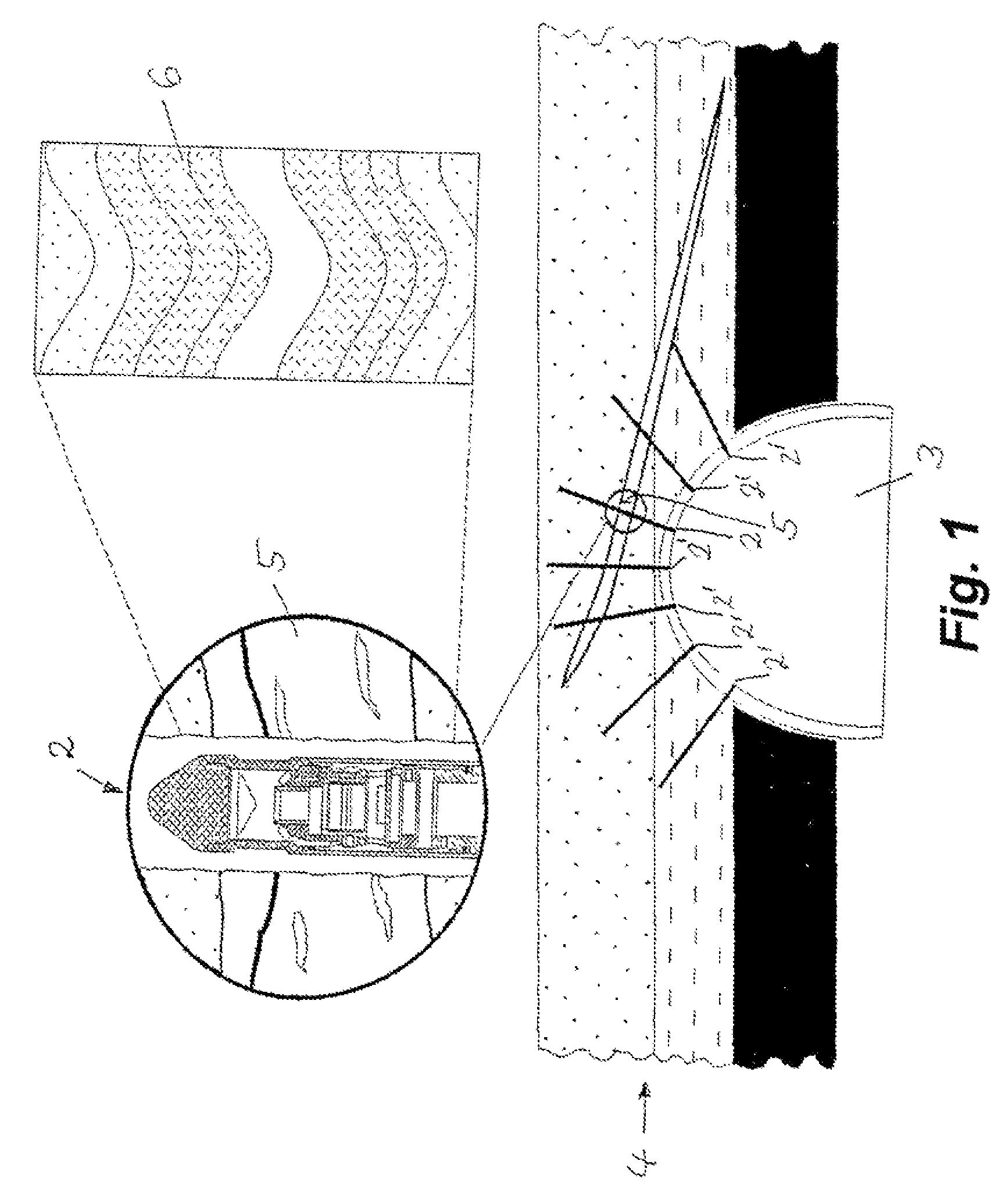
[0016]Using the evaluation program and the database it is possible to compare data from older inspections with more recent inspection results so that changes in the fracture openings can be detected. This prompt recognition of fracture zones makes it possible to take action early on. It is thus possible to assess the rock structure's condition in terms of safety at any time. In addition, information regarding the rock structure's properties is very important during planning and optimization of the path supports and particularly anchor dimensioning. If there are any problems when driving, the anchor borehole can be documented quickly.
[0019]In addition, there are numerous options for graphics processing of the digital images recorded by the probe. The technician can for instance crop the images; change brightness, contrast, intensity, and gamma value; adjust sharpness; and smooth. The images can be rotated and aligned on their axial orientation. In addition there is a clean-up function for eliminating measurement artifacts.
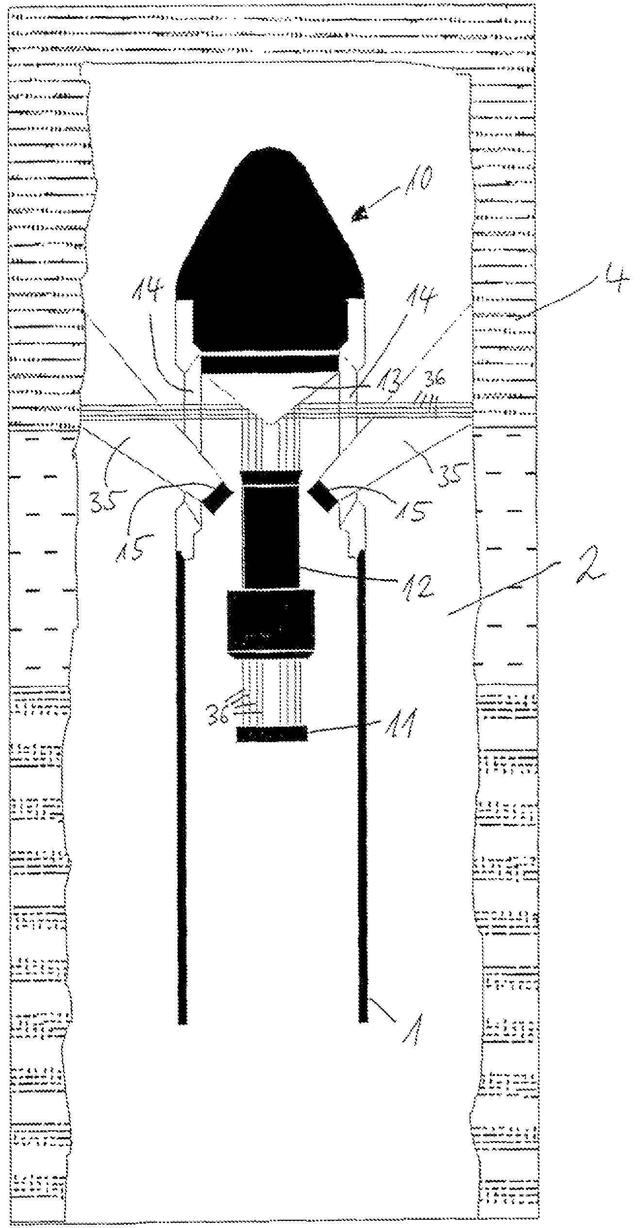
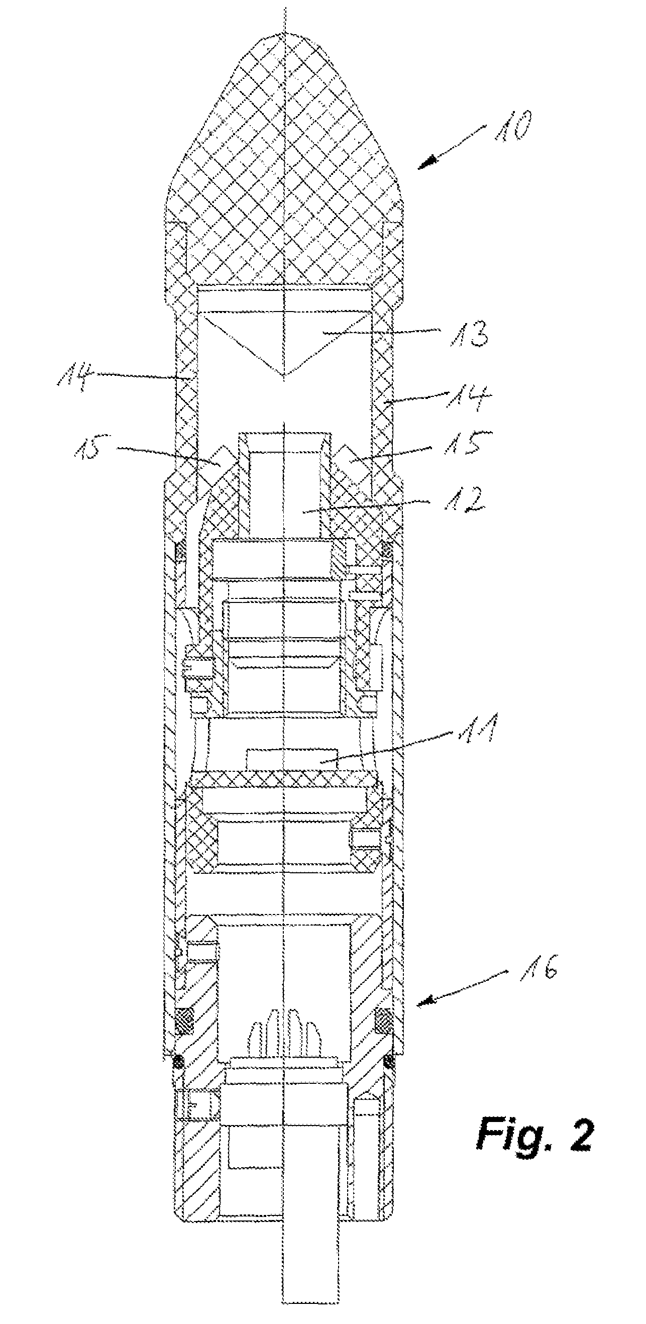
[0025]The borehole probe constitutes a video head, a path sensor, an electronics module, a memory module, and a battery element that also holds an infrared interface. Data transmission makes it possible to monitor inspections.

Problems solved by technology

The methods and apparatuses disclosed in these publications are not suitable for inspecting anchor boreholes because anchor boreholes generally have a diameter of 1 to 2 inches.
With such endoscopy, the borehole wall is visually inspected on-site; it is not possible to store the observation and a true spatial depiction of the layer data for the rock structure.

Method used


Image

  • Device for examining rotor drilled holes
  • Device for examining rotor drilled holes
  • Device for examining rotor drilled holes

Examples


example

[0034]An anchor borehole is inspected with a probe that has the following specifications.

[0035]

Power supply:5 × Duracell MN 1500, 1.5 VData memory:256MBProbe length:1,300mmProbe diameter23mmProbe weight:2.2kgSensor:COLOR CCDMeasurement cycle:Max. 25 images per secondMeasurement speed:Max. 5 cm per secondIllumination:8 white light-emitting diodesDepth measurement:Wheel-driven travel sensor

[0036]The probe is moved along the borehole using a pipe string. Bars built into each coupling ensure good control of the orientation of the probe in the borehole. The anchor-borehole probe scans an angle of 360 degrees, i.e. it covers the entire borehole wall. In the two-dimensional image of the borehole wall surface, which corresponds to a cylinder surface, the borehole wall is shown unrolled. What this leads to is that planar structures, such as e.g. stratum surfaces, fissures, etc. that are not exactly perpendicular to the axis of the borehole appear as sinusoidal lines in this view. The true sp...


PUM

PropertyMeasurementUnit
diametersaaaaaaaaaa
diameteraaaaaaaaaa
diameteraaaaaaaaaa

Abstract

A probe for inspecting an anchor borehole has a video head provided with a color CCD sensor, a lens, a conical viewing window, and light-emitting diode for illuminating and optically scanning a borehole surface. The probe also has a travel sensor, an electronics module including two position sensors, a memory module, and a battery section carrying an infrared interface. The probe is cableless and autarchic. The battery section is secured to a leading end of a push rod.

Description

CROSS REFERENCE TO RELATED APPLICATIONS[0001]This application is the US national phase of PCT application PCT / EP2005 / 005474, filed 20 May 2005, published 08 Dec. 2005 as WO2005 / 116401, and claiming the priority of German patent application 102004026702.2 itself filed 28 May 2004, whose entire disclosures are herewith incorporated by reference.FIELD OF THE INVENTION[0002]The invention relates to an apparatus for inspecting anchor boreholes and comprises a probe that has an optical acquisition device and that can be moved in the borehole with a pipe string.BRIEF DESCRIPTION OF THE DRAWING[0003]U.S. Pat. No. 5,663,559 describes a method and an apparatus for producing an image of an earth formation in oil-prospecting bores.[0004]EP 0658 253 B1 discloses a borehole observation instrument for inspecting the interior of a borehole or shaft in oil prospecting bores.[0005]WO 94 / 07147 A1 relates to a method of and an apparatus for simultaneous video-technical determination of the flow directi...

Claims


Application Information

Patent Timeline
Patent Type & Authority Patents(United States)
IPC IPC(8): G01V5/08G01N21/00G06K9/00E21B47/00E21D20/00H04N5/225
CPCE21B47/0002E21D20/00H04N5/2256H04N2005/2255G01N21/954E21B47/002H04N23/555H04N23/56
Inventor PETERS, STEPHANRAPP, SONKERAKERS, EIKO
Owner DEUTSCHE MONTAN TECHNOLOGIES GMBH
Learn More