Check patentability & draft patents in minutes with Patsnap Eureka AI!

Shading correction method and system and digital camera

a technology of digital cameras and correction methods, applied in the field of lens shading correction, can solve the problems of image dark edges, increase in circuit size, gain control shading correction cannot be applied, etc., and achieve the effect of accurate and flexibl

Inactive Publication Date: 2009-05-26
PANASONIC SEMICON SOLUTIONS CO LTD
View PDF6 Cites 11 Cited by
  • Summary
  • Abstract
  • Description
  • Claims
  • Application Information

AI Technical Summary

Benefits of technology

[0010]It is therefore an object of the present invention that shading correction can be performed by a small-size configuration accurately and flexibly to accord with characteristics of the optical system.
[0012]This enables the correction data to be obtained just by giving data on the sample points for the corresponding segment. Therefore, unlike in the prior art configurations, a ROM or a RAM does not have to be provided, which allows the circuit size to be reduced as compared to the conventional cases. In addition, since the approximation function is divided into the plurality of segments, the desired correction characteristics can be approximated with high accuracy, resulting in the realization of fine correction. Furthermore, since correction characteristics can be changed just by updating data on the sample points for the segments, correction that accords with characteristics of the optical system can be easily realized. Moreover, if the approximation function is established to reflect gain control as well, a gain controller can be omitted for a further reduction in the circuit size.

Problems solved by technology

Specifically, since light enters diagonally in the peripheral area, the amount of incident light per unit pixel is smaller as compared with the central area, causing the image to become dark in the edges.
First, in the configuration of FIG. 8, correction data for shading correction is stored in the ROM. This causes the shading-correction characteristics themselves to be fixed, making it difficult to perform shading correction to accord with characteristics of the optical system. By gain control, it is of course possible to make shading corrections corresponding to individual cases to a certain extent, but in practice that extent is not sufficient for corresponding to various kinds of products, such that gain-control shading correction cannot be applied widely. Furthermore, in addition to the ROM in which a large amount of correction data is stored, a radius operation unit for carry out square calculation, and a gain controller for performing gain control are necessary, which results in an increase in the circuit size.
Secondly, in the configuration in which a ROM is replaced by a RAM, since correction data can be updated easily, shading correction that conforms to characteristics of the optical system can also be realized easily. However, RAMs are larger in circuit size than ROMs. The circuit size of the configuration with a RAM is thus greater that that of the configuration of FIG. 8. Moreover, correction data has to be written into the RAM during system startup, requiring the system to take a long time to start operation.
Thirdly, the configuration disclosed in document 1 realizes shading correction that accords with characteristics of the optical system by including a plurality of ROMs. However, providing the plurality of ROMs, in which a large amount of correction data is stored, results in a larger circuit size as well as higher costs.

Method used


Image

  • Shading correction method and system and digital camera
  • Shading correction method and system and digital camera
  • Shading correction method and system and digital camera

Examples


first embodiment

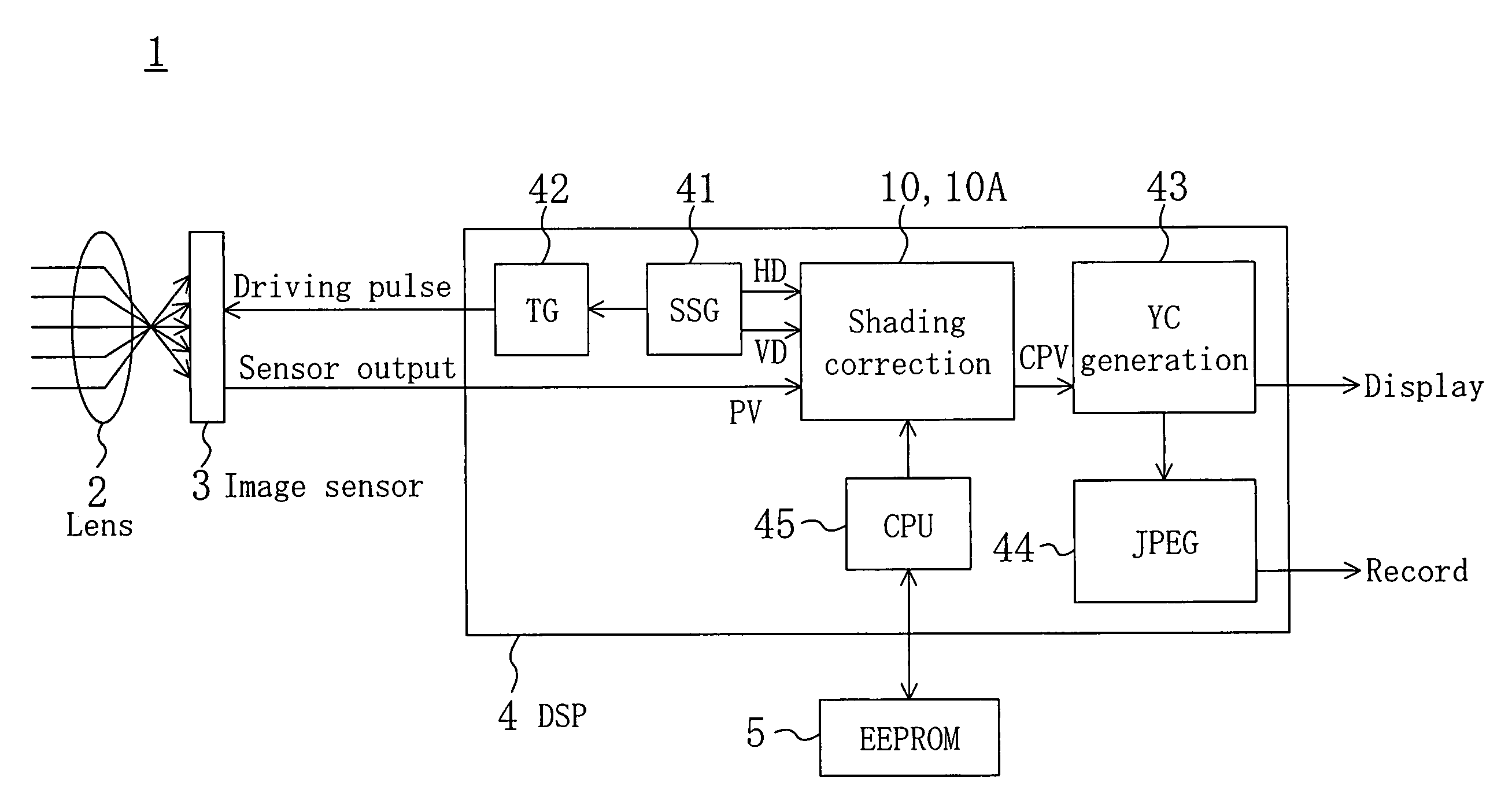
[0030]FIG. 1 is a block diagram illustrating an exemplary system configuration of a digital camera in accordance with the present invention. A digital camera 1 shown in FIG. 1 includes a lens 2, an image sensor 3, a DSP (digital signal processor) 4 having a shading correction block 10, 10A, and an EEPROM (electrically erasable and programmable ROM) 5 for storing therein parameters for shading correction.

[0031]The DSP 4 is provided with a SSG (sync signal generator) 41, a TG (timing generator) 42, a YC generator 43, and a JPEG portion 44. The SSG 41 generates a synchronizing signal. The TG 42 receives the synchronizing signal and supplies a driving pulse to the image sensor 3. The YC generator 43 produces a brightness signal (Y) and a color signal (C) from output from the image sensor 3 in which shading has been corrected. The JPEG portion 44 compresses the brightness and color signals outputted from the YC generator 43. The output signals from the YC generator 43 are displayed on a ...

second embodiment

[0045]FIG. 5 is a block diagram illustrating the inner configuration of the shading correction block 10A, which is a shading correction system in accordance with a second embodiment of the present invention. In FIG. 5, the same members as those shown in FIG. 2 are designated by the same reference numerals.

[0046]In the first embodiment, correction data is calculated from the distance from the optical-axis position. In this embodiment, horizontal-direction correction data HCD and vertical-direction correction data VCD are respectively obtained from a horizontal coordinate value HC and a vertical coordinate value VC with respect to the optical-axis position, and then the correction data HCD and VCD are added together to obtain correction data CD.

[0047]More specifically, in the configuration of FIG. 5, a first correction-data operation unit 15a refers to a first approximation function that indicates relation between horizontal coordinate values and correction data for lens-shading corre...


PUM


Abstract

From horizontal and vertical coordinate values HC and VC of a pixel, a distance operation unit calculates a distance value RV indicating the distance from an optical-axis position to the pixel. A correction-data operation unit receives the distance value RV, and calculates correction data CD for the pixel by referring to an approximation function indicating relation between distance values and correction data. The approximation function is divided into a plurality of segments, and in each segment represented by a quadratic function defined by a predetermined number of sample points.

Description

BACKGROUND OF THE INVENTION[0001]The present invention pertains to technology of correcting lens shading in image data captured by a camera.[0002]“Lens shading” is a phenomenon in which an image taken through an optical lens is bright in the center and darker toward the edges as shown in FIG. 7A. Such phenomenon results from decreases in the amount of light in the peripheral area of an image sensor as shown in FIG. 7B. Specifically, since light enters diagonally in the peripheral area, the amount of incident light per unit pixel is smaller as compared with the central area, causing the image to become dark in the edges. Due to lens shading, output from the image sensor decreases concentrically in the direction going toward the periphery, with an optical-axis position being as the center. Shading characteristics vary depending upon the camera diaphragm value, zoom position, type of lens, etc.[0003]FIG. 8 is a block diagram illustrating an exemplary configuration of a conventional sha...

Claims


Application Information

Patent Timeline
IPC IPC(8): H04N9/64G06K9/40G06T1/00H04N1/401H04N5/243H04N101/00
CPCH04N5/3572H04N25/61
Inventor KAWAKAMI, MAKOTOIWASAWA, TAKAHIROINOKUMA, KAZUYUKITSUMURA, KEIICHITOKUYAMA, KATSUMINAKASHIMA, TOSHIYUKI
Owner PANASONIC SEMICON SOLUTIONS CO LTD
Features
  • R&D
  • Intellectual Property
  • Life Sciences
  • Materials
  • Tech Scout
  • Unparalleled Data Quality
  • Higher Quality Content
  • 60% Fewer Hallucinations
Learn More