However, accurately measuring the functional fmax of an
integrated circuit during production test is relatively difficult.
Localized manufacturing defects and parametric variations can affect the fmax of a device.
Localized manufacturing defects such as relatively resistive vias or pinholes in conductors can cause a particular path to be significantly slower than predicted by design.
If the
delay through the path results in the
signal reaching its target after the
clock edge on which it is sampled, incorrect data will be sampled and the device will not operate properly.
These defects are typically considered to be a reliability
hazard as they can degrade over the lifetime of the product causing an early life failure in the end customer application.
Parametric variations can cause paths to be significantly slower (or faster) than predicted by design, resulting in correspondingly lower or higher fmax of a device.
Given the number of transistors on a deep sub-micron
microprocessor, there can be on-die process variations resulting in paths within a single device varying unpredictably relative to one another, as well as process variations across a
wafer resulting in all paths of some die varying relative to other die, and likewise process variations between wafers and between
wafer lots.
The problem of obtaining sufficient coverage of critical timing paths for accurate fmax determination during production test is expected to get worse over time as deep sub-micron design and fabrication processes continue to be refined.
This results in a plethora of possible critical timing paths ultimately determining the fmax for an individual IC, with the actual critical timing path of a specific die being a function of intra-die random process variations that is difficult to control or measure.
Consequently there is an
increased risk with any kind of fmax testing that “the” critical timing path for a particular device is not correctly exercised, resulting in the particular device being incorrectly placed in a higher performance bin, leading to failure in a customer application, i.e., production test escapes.
For example, test development cost can be driven by the
engineering challenges of guaranteeing test coverage of critical timing paths, “cyclizing”
test bench stimulus and device response to fit the constraints of ATE performance, and wasted resources due to debug time after prototype
silicon is available.
These problems are exacerbated with deep sub-micron
system-on-
chip (SOC) devices with large numbers of critical timing paths, multiple asynchronous interfaces and non-deterministic device output even for defect-free samples due to, for example, signals crossing (multiple) asynchronous
clock domain boundaries, phase /
frequency locked loop (PLL) sourced core clocks operating with non-deterministic phase relative to device input clocks, and the like.
Long-term
impact on device profitability comes from the lose-lose tradeoff of yield loss versus risk of specification violations and customer returns, along with the risk of test escapes due to less than 100% at-speed coverage of critical timing paths.
For example, if test limits are set conservatively to guard against ATE inaccuracy, some parts will typically be down-binned into a lower
speed grade (yield loss) than they are capable of performing, resulting in reduced revenue.
If test limits are set aggressively to minimize yield loss, then some parts will typically be up-binned into a higher
speed grade than they are capable of performing, resulting in potential failure in a customer application.
This issue can be compounded by the difficulty in guaranteeing that the functional vectors used for speed-binning properly exercise the worst-case path(s) on all parts.
For example, it is possible that the
speed grade determined during production test is valid for the functional
modes tested, but in a particular customer application, a path which was not speed tested dominates, which results in a field failure and customer return.
The foregoing correlation is typically not sufficiently robust to be used as the sole
determinant for speed-binning a device.
This is not unexpected, given on-die
process Variation and difficulties in obtaining sufficient test coverage of critical timing paths.
While process monitors can provide information on the average process speed for a given device, they generally provide insufficient information on the relatively localized intra-die process variations that ultimately determine which path on a device limits the functional fmax.
Unfortunately, there are many problems in correlating fmax measured using AC scan vectors with fmax measured using functional vectors and / or with fmax measured in a
system environment.
The problems are generally attributed to the difficulty in obtaining relatively high
path delay fault coverage of critical timing paths, particularly in microprocessors with
embedded memory arrays.
As with the other methods discussed, failure to provide 100% coverage of all possible critical timing paths can result in a risk of placing devices in a higher speed-bin than is appropriate, leading to field failures and customer returns.
An attempt to measure a peak-to-peak range-will typically not yield a reproducible result, regardless of sample size.
Typically, more measurements simply result in more opportunities for measuring an
outlier value and no improved knowledge of the accuracy or
repeatability of the peak-to-peak measurement.


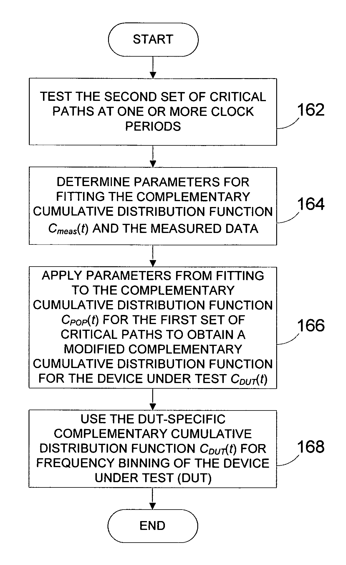
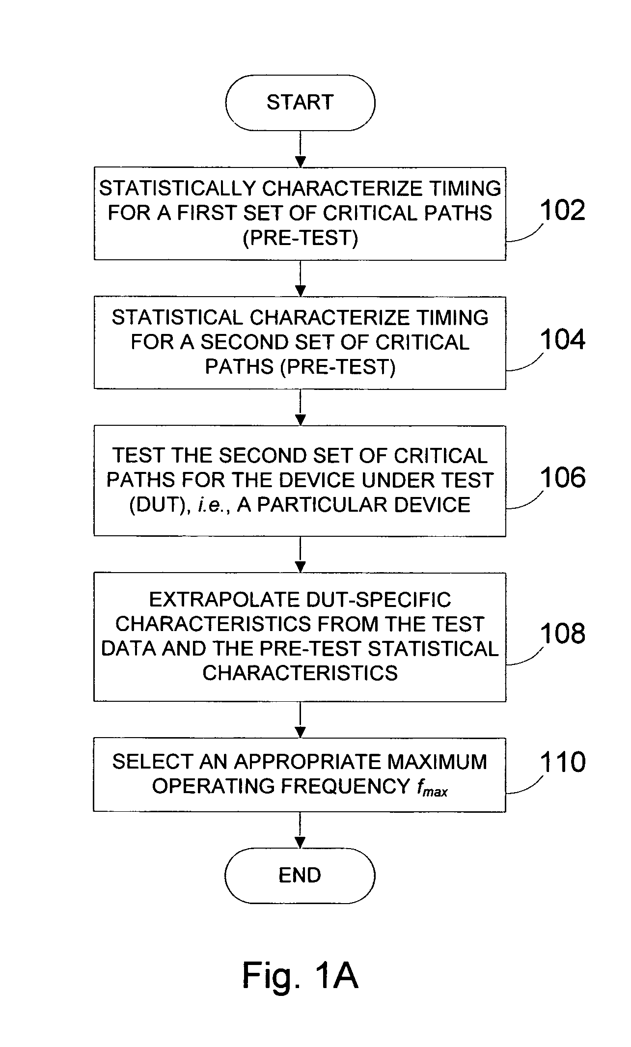
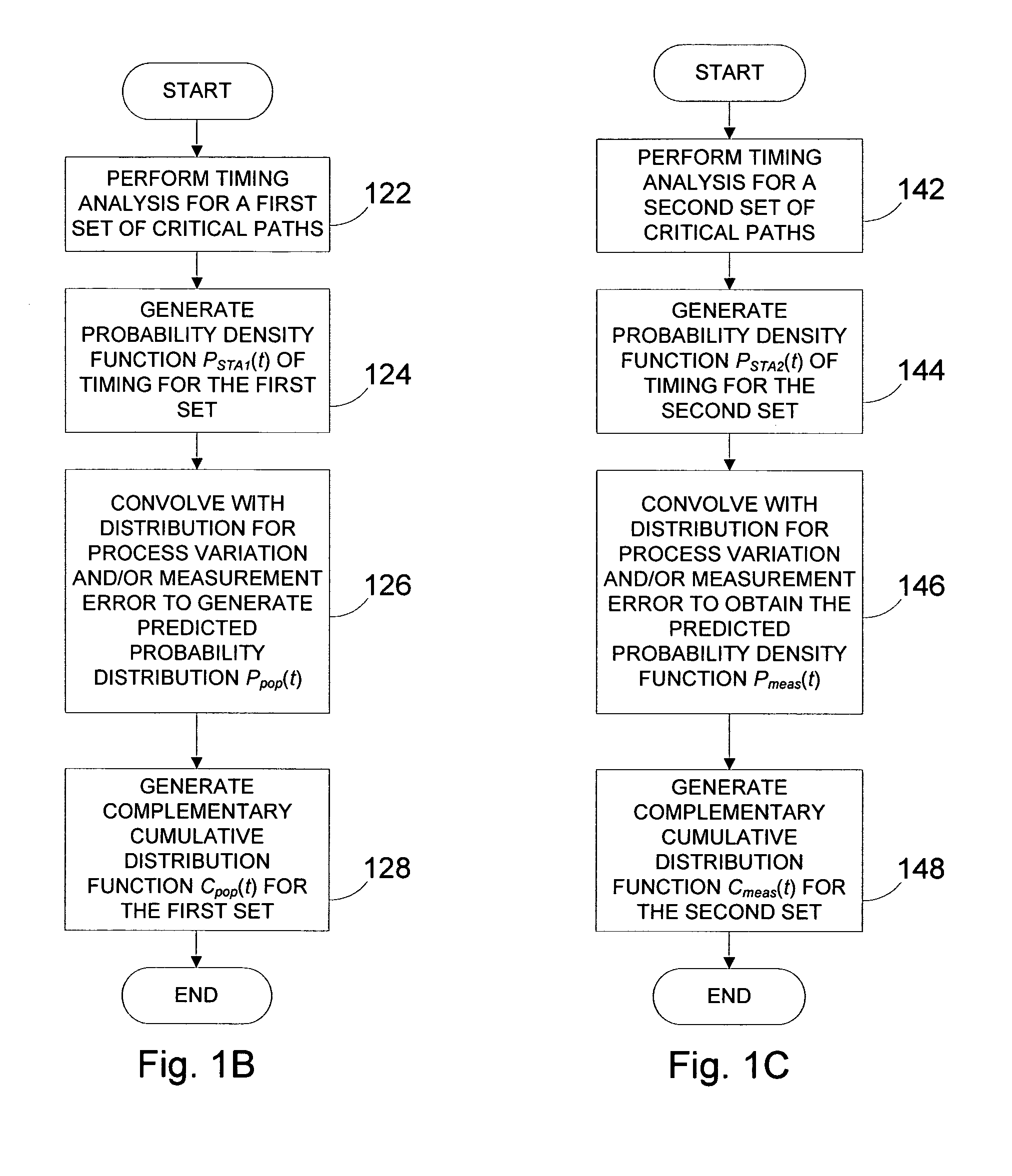