Method and a system of diagnosing corrosion risk of a pipe or a pipeline in soil

a technology of corrosion risk and method, applied in the field of detection of corrosion of catho, can solve problems such as inability to provide reliable criteria, and achieve the effect of reducing thickness

Active Publication Date: 2009-06-02
METRICORR
View PDF12 Cites 17 Cited by
  • Summary
  • Abstract
  • Description
  • Claims
  • Application Information

AI Technical Summary

Benefits of technology

[0054]It is an advantage of the present invention that the technique of diagnosing corrosion risk of a pipe or a pipeline buried in soil due to DC stray currents and / or AC voltages induced in the soil may be carried out based on a simple combination of current and voltage measurements and calculating specific resistances in accordance with Ohms's Law for determining reproducible parameters readily combinable according to an empirical scheme for diagnosing the corrosion risk.
[0055]The technique according to the present invention involves probes electrically connected to the pipeline, and an instrumentation to be installed in a standard measuring post. In a presently preferred embodiment, the instrumentation may control and store data from three such probes. The probes are buried in the soil and the electrical connection to the pipe is made in the instrumentation positioned (for instance) in the standard measuring post.
[0056]The probes constitute typically two (or more) metal elements, most often initially identical, built into an ER (electrical resistance) probe. One element (denoted hereafter the coupon element, C) is exposed in the hostile environment and diminishes in thickness due to corrosion. The resistance of the coupon element (RC) changes primarily with thickness and temperature. A second element (denoted hereafter the reference element, R) is shielded from the hostile environment, e.g. by coating. The resistance of the reference element (RR) changes primarily with temperature and the element is used for compensation of this effect. The probe is used for measurements of the corrosion rate and degree of accumulated corrosion according to procedures e.g. described in previous patent application publication number WO 01 / 42764.
[0057]According to a pre-programmed time schedule, the instrument wakes up and performs a series of measurements on the probe(s). Firstly, the AC current (Iclosed) flowing between the pipe and the individual probe is measured.
[0058]Secondly, one probe at a time is disconnected from the pipe, and the AC voltage between the pipe and the probe is measured (Vopen).
[0059]Thirdly, in the disconnected condition, the instrumentation measures the resistance of the (two) elements of an ER probe. Excitation current is passed through the elements, and a data acquisition system picks up the voltages generated across the elements and scales this properly into a measure of the element resistances, RC and RR. The electrical connection between the pipe and the probe is then re-established, and the instrumentation continues to address the remaining probes.

Problems solved by technology

Usual acceptance criteria (safe / not safe with regard to corrosion) are built upon the DC potential of the pipeline, but specifically in the case of AC induced corrosion, these criteria are not reliable.

Method used


Image

  • Method and a system of diagnosing corrosion risk of a pipe or a pipeline in soil
  • Method and a system of diagnosing corrosion risk of a pipe or a pipeline in soil
  • Method and a system of diagnosing corrosion risk of a pipe or a pipeline in soil

Examples


Embodiment Construction

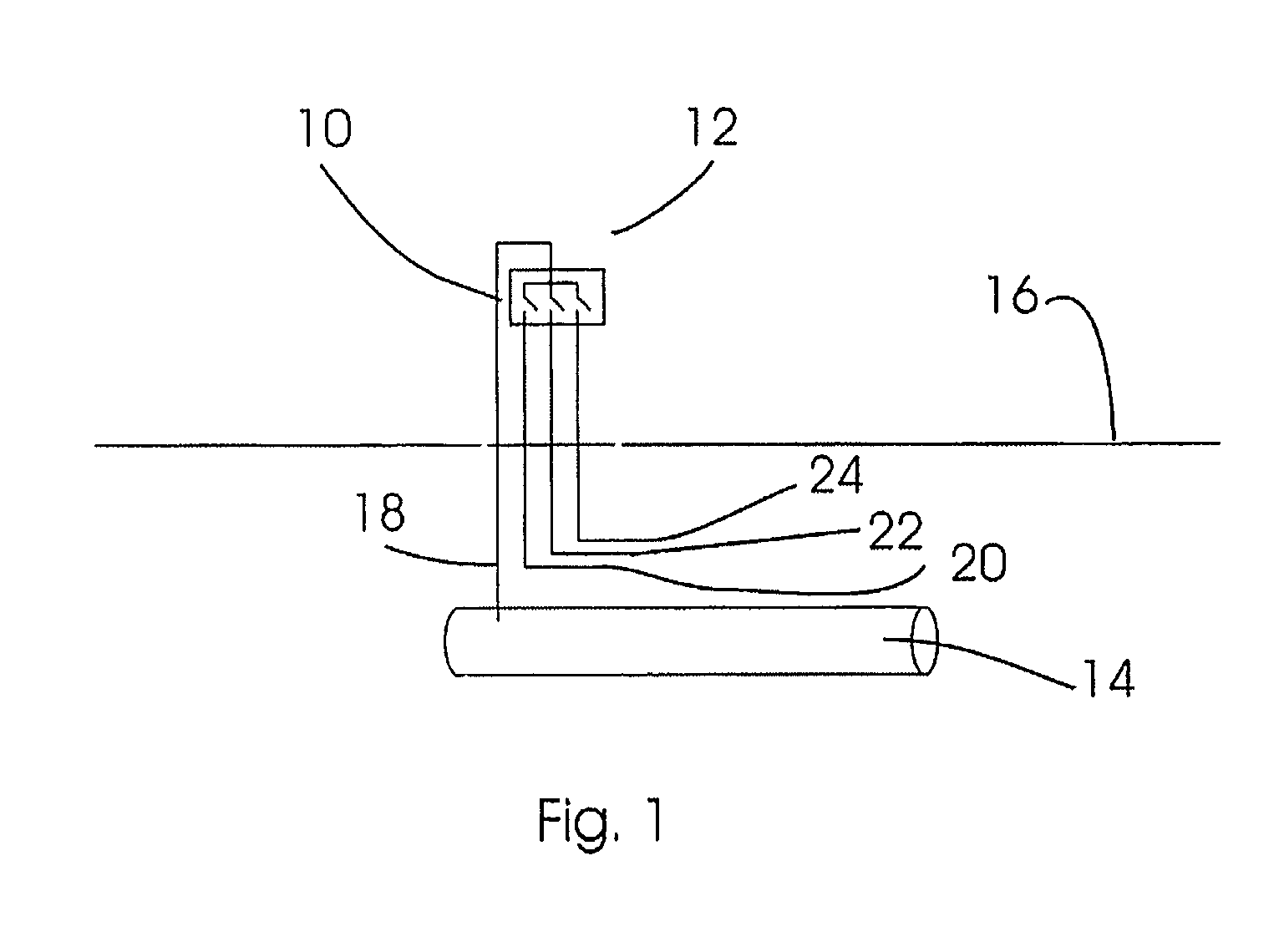
[0083]FIG. 1 illustrates the schematic set-up of the measurement system according to the present invention. The measurement system 10 is placed inside a measuring post 12. Measuring posts are placed along high pressure pipelines such as illustrated by a piece of a pipeline 14 buried beneath the surface of the ground 16. As the pipelines are usually placed along high voltage power lines, the measuring post 12 may also comprise measuring instruments for measuring and monitoring the performers of the high voltage power lines.

[0084]The measurement system 10 has at least one electrical connection to the buried pipeline 14 constituted by an electrical wire 18. Buried in the ground, preferably parallel to the pipeline 14 are at least one probe and preferably three probes designated the numerals 20, 22, 24.

[0085]The measuring system 10 may also be placed in a specialised post separate from the standard measuring post 12.

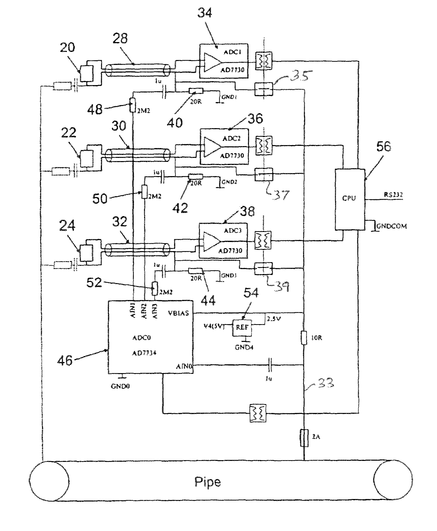
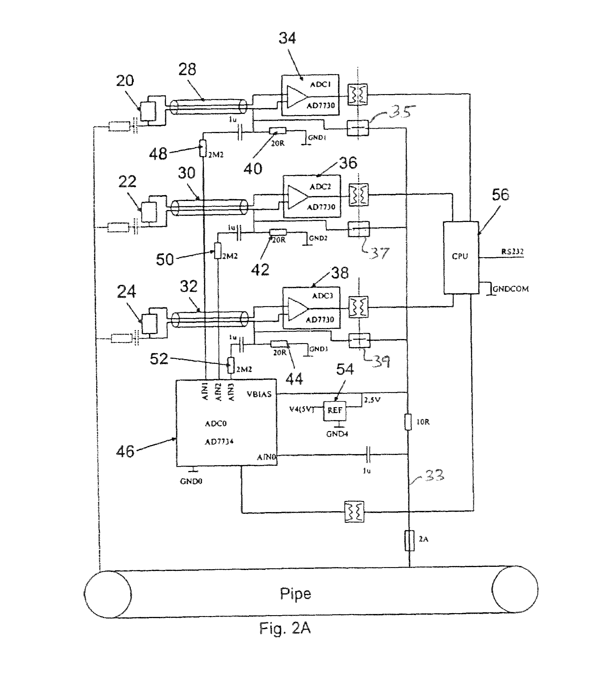
[0086]FIG. 2a is a schematic representation of the measurement system 1...


PUM

PropertyMeasurementUnit
spread resistanceaaaaaaaaaa
voltageaaaaaaaaaa

Abstract

A method of diagnosing corrosion risk of a buried pipe due to DC stray currents and / or AC voltages induced in soil employs a metal probe including a first, exposed part having a first specific resistivity, and a second, sealed reference part having a second specific resistivity. The probe is buried in the soil, and the AC current and voltage between the pipe and the probe are measured, from which the spread resistance is determined. The resistances of the first and second probe parts are determined by respectively passing first and second excitation currents through the first and second probe parts and measuring the voltages across them. The resistance measurements are stored, and the steps are repeated periodically. The corrosion of the first probe part is determined from the measurements according to an algorithm, and the pipe corrosion risk is diagnosed from an empirical combination of the corrosion of the first probe part, the spread resistance, and the AC voltage measured.

Description

CROSS-REFERENCE TO RELATED APPLICATIONS[0001]This application is the national phase, under 35 U.S.C. §371(c), of PCT / DK2005 / 000142, filed 1 Mar. 2005, the disclosure of which is incorporated herein by reference.FEDERALLY SPONSORED RESEARCH OR DEVELOPMENT[0002]Not ApplicableBACKGROUND OF THE INVENTION[0003]The present invention relates to detection of corrosion of cathodically protected, CP, buried pipelines by use of probes buried in the soil adjacent to the pipelines and electrically connected to the pipelines. More specific, the invention relates to detection of corrosion caused by the combined effect of specific soil parameters and electric fields such as DC stray current or AC voltage induced as a result of paralleling the pipeline with high voltage power lines. Such corrosion is sometimes found to proceed although measures have been taken to eliminate the corrosion effects, e.g. by imposing DC current to the pipeline by an external electrode and a rectifier system, or by sacrif...

Claims


Application Information

Patent Timeline
Patent Type & Authority Patents(United States)
IPC IPC(8): G01R27/08G01N17/02G01N17/04G01N27/04
CPCG01N17/02
Inventor NIELSEN, LARS V.GALSGAARD, FOLKE
Owner METRICORR
Why Eureka
Try Eureka