System and method for high-resolution with a small-format focal-plane array using spatial modulation

a technology of spatial modulation and focal plane, applied in the field of system and method for high-resolution with a small-format focal-plane array using spatial modulation, can solve the problems of imposing a processing sensing and processing load that is often impractical to bear, and achieves a high level of clutter suppression, maximize the use of all output frames, and reduce processing load

Inactive Publication Date: 2009-06-02
AERODYNE RES
View PDF5 Cites 37 Cited by
  • Summary
  • Abstract
  • Description
  • Claims
  • Application Information

AI Technical Summary

Benefits of technology

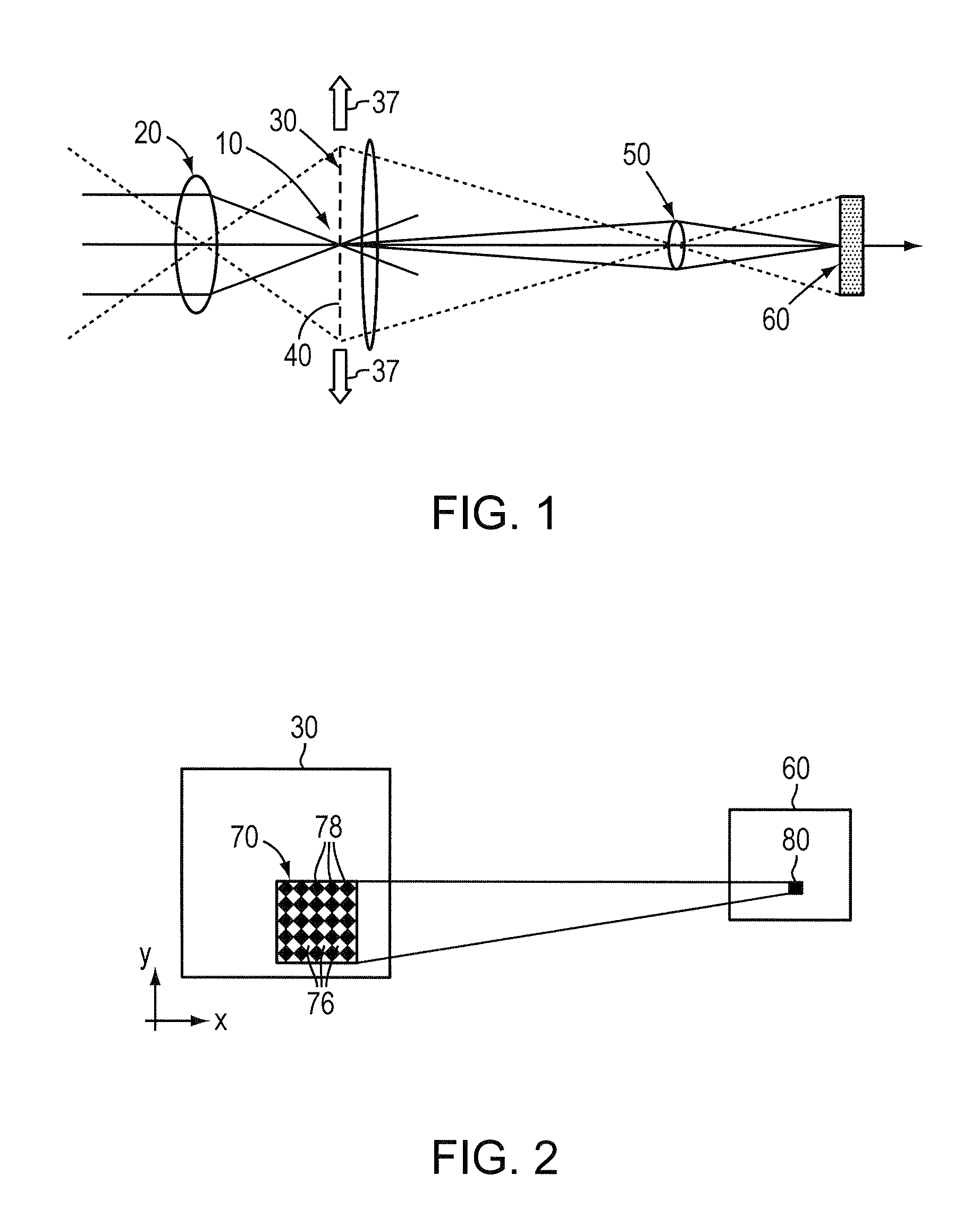
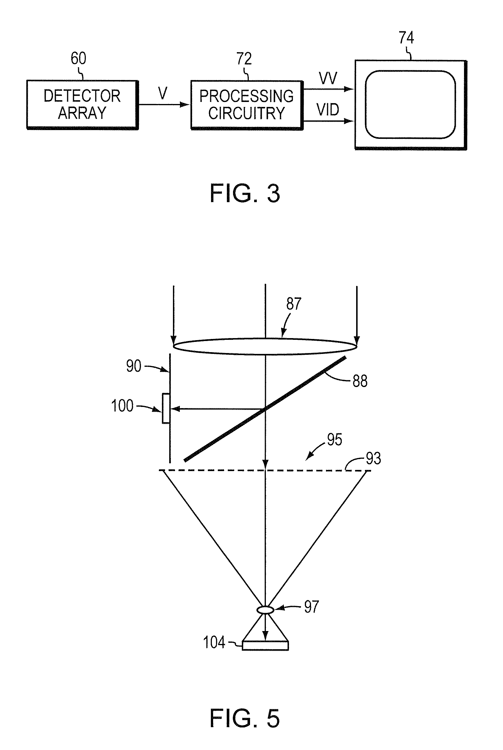
[0027]A spatial-modulation staring sensor is able to perform point target detection with a much smaller-format focal plane array FPA than would otherwise be required. Conventionally, though, the frame rate required for it to perform effectively for rapidly moving scenes, such as those observed from a rapidly maneuvering aircraft, can impose a processing sensing and processing load that is often impractical to bear. Unless the frame rate is high, the magnitude of the residual clutter increases sharply when the clutter is moving with respect to the sensor. One approach to reduce the processing load is to employ “balanced-demodulation procedures.” A system that employs balanced demodulation moves a chopping reticle located in the intermediate focal plane where front-end optics focuses a high-resolution image. The chopping reticle has a checkerboard pattern of clear and opaque cells and moves in an uneven rate (e.g. Δx≠Δy) along the x-axis and y-axis. The exemplary chopping reticle has a checkerboard pattern of clear and opaque cells and moves in an uneven rate (e.g. Δx≠Δy) along the x-axis and y-axis. The resulting reticle-modified image is projected on a focal plane array from which differences are calculated to generate the desired balanced demodulation value. Using such procedures in place of the types of procedures previously employed in spatial-modulation staring sensors tends to preserve a high level of clutter suppression with scene motion without requiring an excessive frame rate. An illustrative embodiment, employs such procedures in ways that implement infinite-impulse-response filtering, maximizes the use of all output frames, and, by summing absolute values rather than taking the square root of the sum of the squares, reduce the computation burden. The necessary frame rate can also be limited by basing reticle motion on target motion.
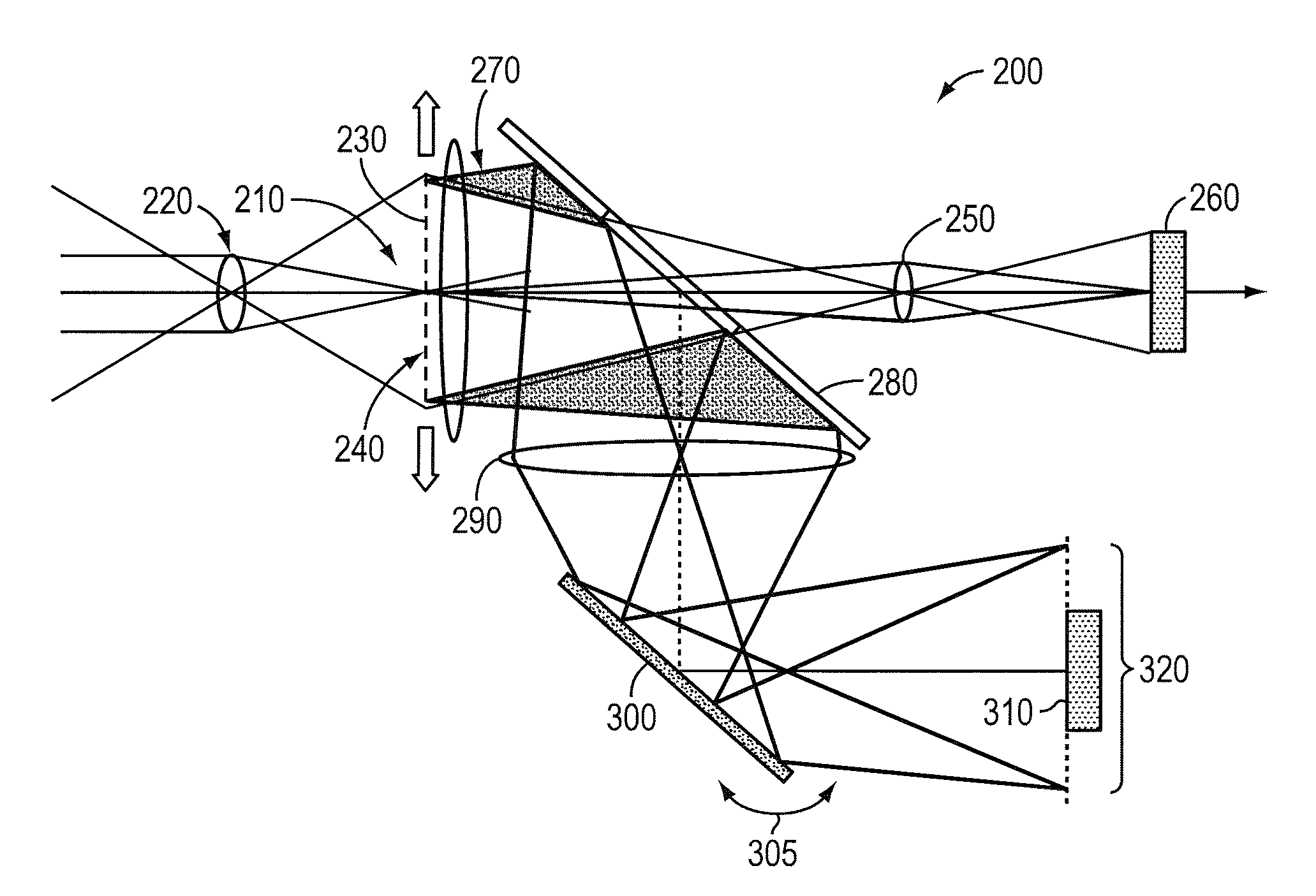
[0030]The detection and recognition of targets over a WFOV requires high-resolution. Conventionally this high-resolution is provided by a high pixel density sensor having a correspondingly high density FPA. SMI provides the high-resolution needed for target detection, but with many fewer pixels and a correspondingly much smaller FPA. Foveal Enhanced Imaging (FEI) is a means of examining a target, detected initially by SMI as an unresolved point target (hot spot), by conventional imaging at high pixel density over a small FOV at that target. Spatial Modulation plus FEI enables targets to be detected and then examined using many fewer pixels (detector elements) than would otherwise be needed.
[0032]Foveation is used by human vision to very efficiently perform the two important tasks of WFOV surveillance to detect objects of interest of any size without detailed recognition capability (by peripheral vision), and NFOV conventional high-resolution imaging of an acquired region of interest or target (by foveal vision). SMI performs an analogous function to that of peripheral vision—sensing of high-resolution detail for cueing of unresolved point targets, without detailed point-by-point imaging as would be needed for recognition. Foveated SMI adds the foveal component (either as pseudo-foveation or true foveation) that allows a detected target to be examined in detail in a conventional high-resolution image of the target and / or its immediate surroundings.

Problems solved by technology

Conventionally, though, the frame rate required for it to perform effectively for rapidly moving scenes, such as those observed from a rapidly maneuvering aircraft, can impose a processing sensing and processing load that is often impractical to bear.

Method used


Image

  • System and method for high-resolution with a small-format focal-plane array using spatial modulation
  • System and method for high-resolution with a small-format focal-plane array using spatial modulation
  • System and method for high-resolution with a small-format focal-plane array using spatial modulation

Examples


Embodiment Construction

[0045]Those skilled in the art and having the benefit of this disclosure will appreciate that the descriptions herein are by way of illustration of the principles of the invention in each case and not by way of limitation.

1. Balanced Demodulation Procedures

[0046]The function of the demodulation procedure is to derive a spatial-modulation output image VV(x,y) in which unresolved point targets are preserved at close to full intensity, whereas all other scene (i.e., clutter) detail is strongly suppressed.

[0047]With the previously referenced baseline procedure, clutter is strongly suppressed when the clutter is not moving relative to the sensor. However, the level of the residual clutter increases sharply as a function of relative scene motion. I have recognized that a high level of clutter suppression can be achieved despite a certain degree of scene motion if one employs a so-termed “balanced demodulation procedure.”

[0048]As described above, a previously used type of demodulation func...


PUM


Abstract

This invention provides a system and method for balanced-demodulation procedures that remove image clutter even in the presence of scene motion. A system that employs balanced demodulation moves a chopping reticle located in the intermediate focal plane where front end optics focus a high-resolution image. The chopping reticle has a checkerboard pattern of clear and opaque cells and moves in an uneven rate (e.g. Δx≠Δy) along the x-axis and y-axis. The resulting image is projected on a focal plane array from which differences are calculated to generate the desired balanced demodulation value. This invention further provides a foveal enhancement of the baseline spatial-modulation staring sensor. In this enhancement the WFOV low-resolution conventional image is displayed to the operator, but with a selectable subarea of that image replaced by a conventionally generated high-resolution image at the same scale. The operator would be able to naturally select the region for foveal enhancement by simply pointing directly at the detail of special interest which would then be displayed to the user at high-resolution. The remainder of the scene would be displayed at low-resolution, typically with marks at the locations of point sources detected by the spatial modulation.

Description

CROSS-REFERENCE TO RELATED APPLICATION[0001]The present application claims the benefit of U.S. Provisional Patent Application Ser. No. 60 / 456,836, which was filed on Mar. 21, 2003 by John Merchant for HIGH-RESOLUTION IMAGING WITH A SMALL-FORMAT FOCAL-PLANE ARRAY USING SPATIAL MODULATION, and is hereby incorporated by reference.STATEMENT REGARDING FEDERALLY SUPPORTED RESEARCH OR DEVELOPMENT[0002]This invention was made with government support under Air Force Contract No. F33615-99-C-1422. The government has certain rights in this invention.BACKGROUND OF THE INVENTION[0003]1. Field of the Invention[0004]This invention relates generally to the detection of unresolved point targets in clutter using a Spatial Modulation staring array image sensor that could incorporate Foveal Enhanced Imaging.[0005]2. Background Information[0006]Detection of unresolved point targets in clutter using an imaging electro optical (EO) or infrared (IR) sensor is required by many military and civilian system a...

Claims


Application Information

Patent Timeline
Patent Type & Authority Patents(United States)
IPC IPC(8): H04N5/235G02B27/10G03B17/10H04N5/225
CPCG02B27/58G03B17/10H04N5/23232H04N5/23248H04N5/33H04N23/951H04N23/68
Inventor MERCHANT, JOHN
Owner AERODYNE RES
Why Eureka
Try Eureka