Method of determining path maximum transmission unit

a transmission unit and path technology, applied in the field of computer network processing, can solve the problems of best-effort, unreliable, and unreliable network protocols, and limiting the maximum tcp performance accordingly

Active Publication Date: 2009-06-02
CITRIX SYST INC
View PDF144 Cites 160 Cited by
  • Summary
  • Abstract
  • Description
  • Claims
  • Application Information

AI Technical Summary

Problems solved by technology

IP is a connectionless, best-effort, unreliable, routable networking protocol.
Other phenomena may limit performance below what the model provides as a maximum.
For example, if the receiver does not advertise a window that is at least as large as the bandwidth delay product of the connection, then maximum TCP performance will be limited accordingly.
Standard implementations of TCP are also known to perform poorly in certain environments and / or conditions.
For example, the high rate of packet loss in typical wireless links results in poor TCP performance.
However, this is frequently not a viable option such as when the source code is unavailable or when there are too many endpoints to conveniently manage.
This technique suffers from at least two disadvantages: firstly, the extra expense of the additional processing node and its associated administrative overhead; and secondly, the PEP often requires redundant processing due to the poor integration with the other nodes of the network.
Even with access to the source code of an operating system, the operational issues associated with supplying and supporting customized versions of the operating system make this prohibitive in many environments.
Requiring large amounts of these resources not only increases system expense, but requires additional environment attention (more power, more space, etc.) and also reduces overall system reliability.
Some prior art techniques translate the TCP / IP protocol into other protocols (e.g., User Datagram Protocol (UDP)), causing disruption to network monitoring, traffic shaping, Quality of Service (QoS), Service Level Agreement (SLA), statistics measuring applications, and others; they also require modifications to firewall and security settings due to the usage of protocols that were not previously employed.
Across all of these dimensions, no algorithm can be optimal.
The transcoding from FTP to UDP interferes with any network element that might attempt to process the individual TCP connection, such as QoS, SLA or traffic management.
However, general-purpose lossless data compression is typically limited to a two- to three-times reduction in data, placing an upper limit on the total performance improvement that can be provided by this technique.
Further, many data types are already compressed, wasting system resources attempting any further compression for these data types.
The computational expense of this method requires the addition of an extra box to the network and limits the speed at which packets can be processed.
The product does not address the fundamental limits of the TCP / IP protocol and is thereby permanently limited to a maximum of two- to three-times performance improvement over offerings without the PEP.

Method used


Image

  • Method of determining path maximum transmission unit
  • Method of determining path maximum transmission unit
  • Method of determining path maximum transmission unit

Examples


embodiment

Preferred Embodiment

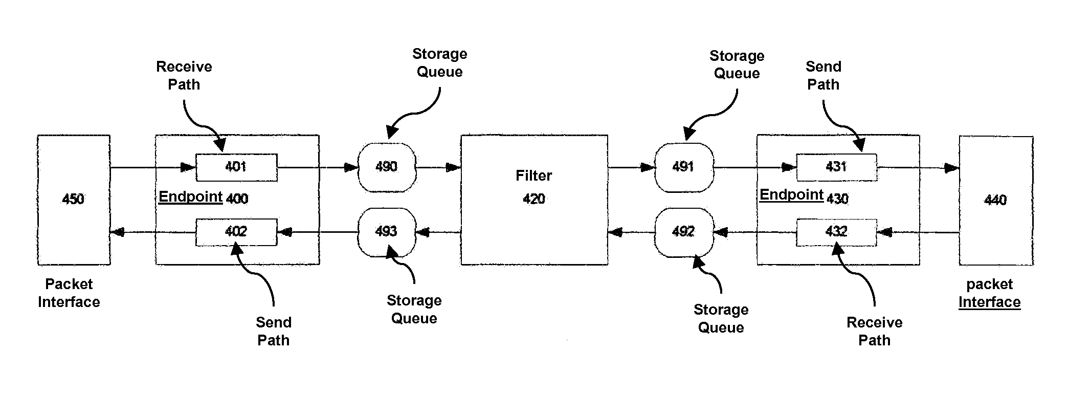
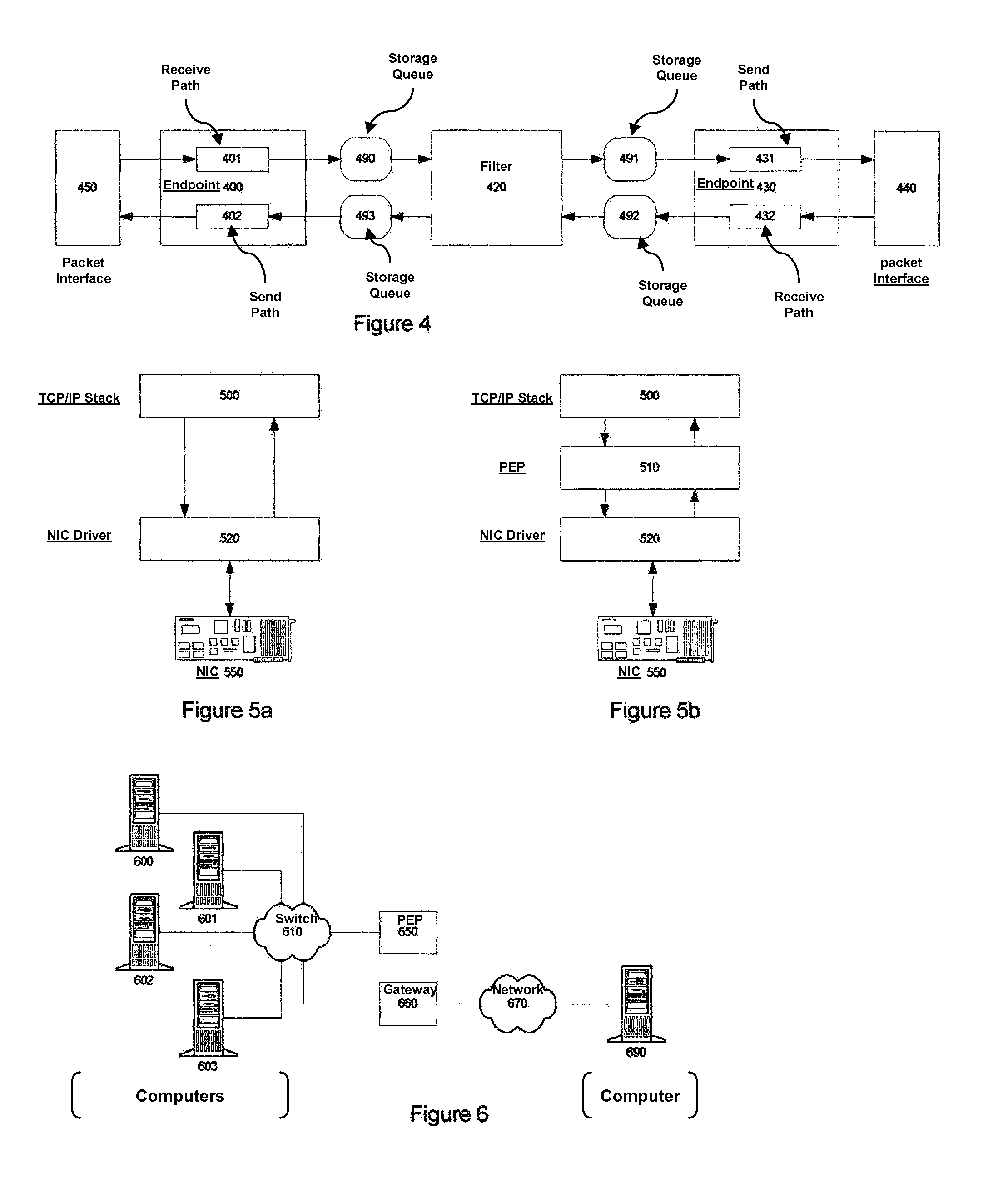
[0115]FIG. 4 shows the architecture of a preferred embodiment of a PEP. The depicted PEP is symmetrical, in that data can flow in either direction. For a first direction of data flow, packet interface 450 receives packets from a network and forwards them to endpoint 400. Endpoint 400, operating as described below, contains receive path 401, which delivers data to storage queue 490. Filter 420 removes data from storage queue 490 and processes it as described below. Filter results destined for the same data flow direction are placed into storage queue 491. Endpoint 430, containing send path 431, removes data from storage queue 491, packetizing it for delivery to a network via network interface 440.

[0116]Note that storage queue 490 may be required only for certain implementations of filter 420. Some implementations of filter 420 may not require retaining inbound data, in which case, the storage queue is unnecessary. Other implementations of filter 420 may provide st...


PUM


Abstract

Network endpoints using TCP / IP operate to determine the maximum transmission unit (MTU) of the path between them. This determination is done so as to avoid the expensive IP fragmentation that will occur when transitioning links with a smaller MTU size. The standard method of determining the path MTU (PMTU) has several known deficiencies, including: inefficient use of bandwidth as proper operation will likely result in the loss of one or more packets and difficulty of implementation as the reverse channel communication mechanism, reception of ICMP messages indicating the discarding of unfragmentable packets, is frequently blocked by firewalls and other security apparatus. A method of determining the PMTU between intermediate proxies is disclosed that does not require reception of ICMP messages or the inefficient use of bandwidth due to the presumed dropping of packets with valid data.

Description

RELATED APPLICATIONS[0001]This application is made subsequent to provisional application No. 60 / 422,801, filed on Oct. 30, 2002 and claims priority of it.FIELD OF INVENTION[0002]This invention pertains to the field of the processing of computer networks, networking equipment and networking protocols, in particular to systems that enhance the performance of existing networking applications through the deployment of additional networking entities known as proxies.BACKGROUND[0003]Many computer networking technologies and protocols are well known. One of the most widely used protocols is the internet protocol (IP). IP is a connectionless, best-effort, unreliable, routable networking protocol. Applications that require reliable communications typically use the Transmission Control Protocol (TCP) on top of IP. The TCP protocol layer provides required functionality such as flow control, packet loss detection, lost packet retransmission, congestion avoidance, etc. (hereinafter referred to a...

Claims


Application Information

Patent Timeline
Patent Type & Authority Patents(United States)
IPC IPC(8): H04L12/28H04L29/06H04L29/08
CPCH04L69/16H04L69/166H04L67/28H04L67/2876H04L67/56
Inventor SAMUELS, ALLENSUTTER, PAUL
Owner CITRIX SYST INC
Why Eureka
Try Eureka