
Electromagnetic response model with improved high frequency stability

a high-frequency stability, electromagnetic response technology, applied in pulse manipulation, pulse technique, instruments, etc., can solve the problems of inability to model much less easily, inability to eliminate time domain instability, and only marginal increase in the stability of peec model approaches, so as to minimize high-frequency instabilities in electromagnetic models, minimize high-frequency instabilities, and extend the frequency range of electromagnetic models

Inactive Publication Date: 2009-06-09
GLOBALFOUNDRIES INC
View PDF4 Cites 0 Cited by
  • Summary
  • Abstract
  • Description
  • Claims
  • Application Information

AI Technical Summary

Benefits of technology

The invention aims to improve the modeling of electromagnetic response by extending the frequency range and minimizing high frequency instabilities. It uses low pass filtered coupled supplies and models high frequency instabilities with a series resistance. This results in a more accurate and reliable model for predicting electromagnetic response in conductors and dielectrics.

Problems solved by technology

Electromagnetic responses in these same physical structures are equally well known, but are much less easily modeled.
However, typical state of the art PEEC models (as well as other time domain integral equation models / solutions) are known to include instabilities above factive, also known as late time instability where factive is the highest frequency of interest for the modeling.
Unfortunately, previous attempts to eliminate this time domain instability have met with only partial success.
Consequently, these approaches have only marginally increased PEEC model stability.
This high frequency instability problem causes an exponential increase in the time domain response.
Including damping resistors further adds to the network complexity and, accordingly, increases computer resources needed for processing the increasingly complex model.
Further, for higher performance applications, where the switching signal spectrum approaches factive and, correspondingly, signal edge rise and fall times decrease dramatically, model instabilities are inevitable using these prior art electromagnetic models.

Method used


Image

  • Electromagnetic response model with improved high frequency stability
  • Electromagnetic response model with improved high frequency stability
  • Electromagnetic response model with improved high frequency stability

Examples


Embodiment Construction

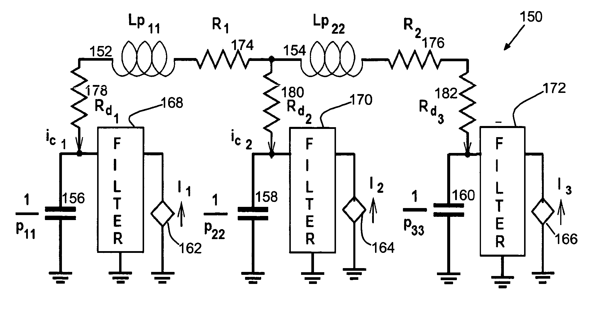
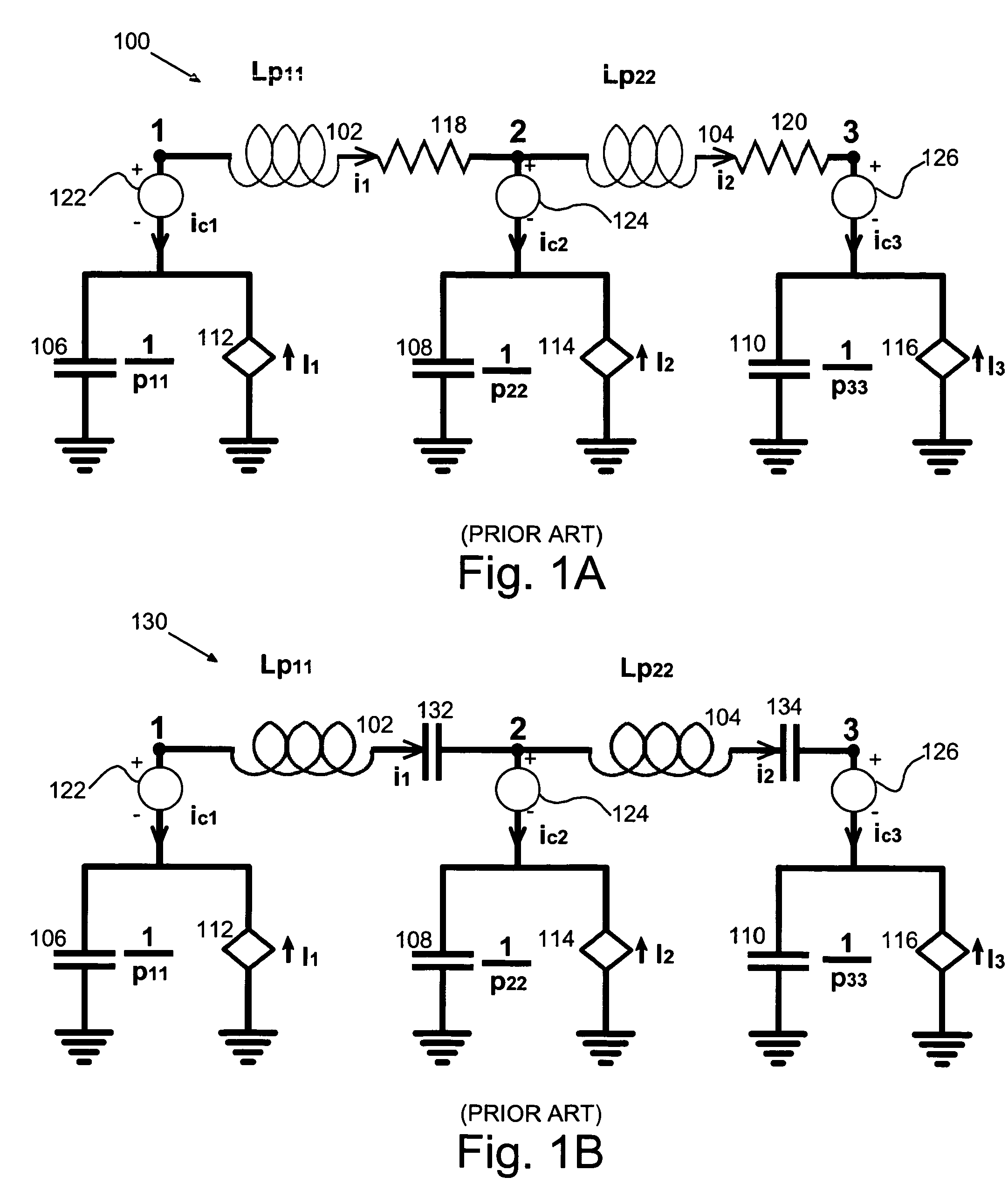
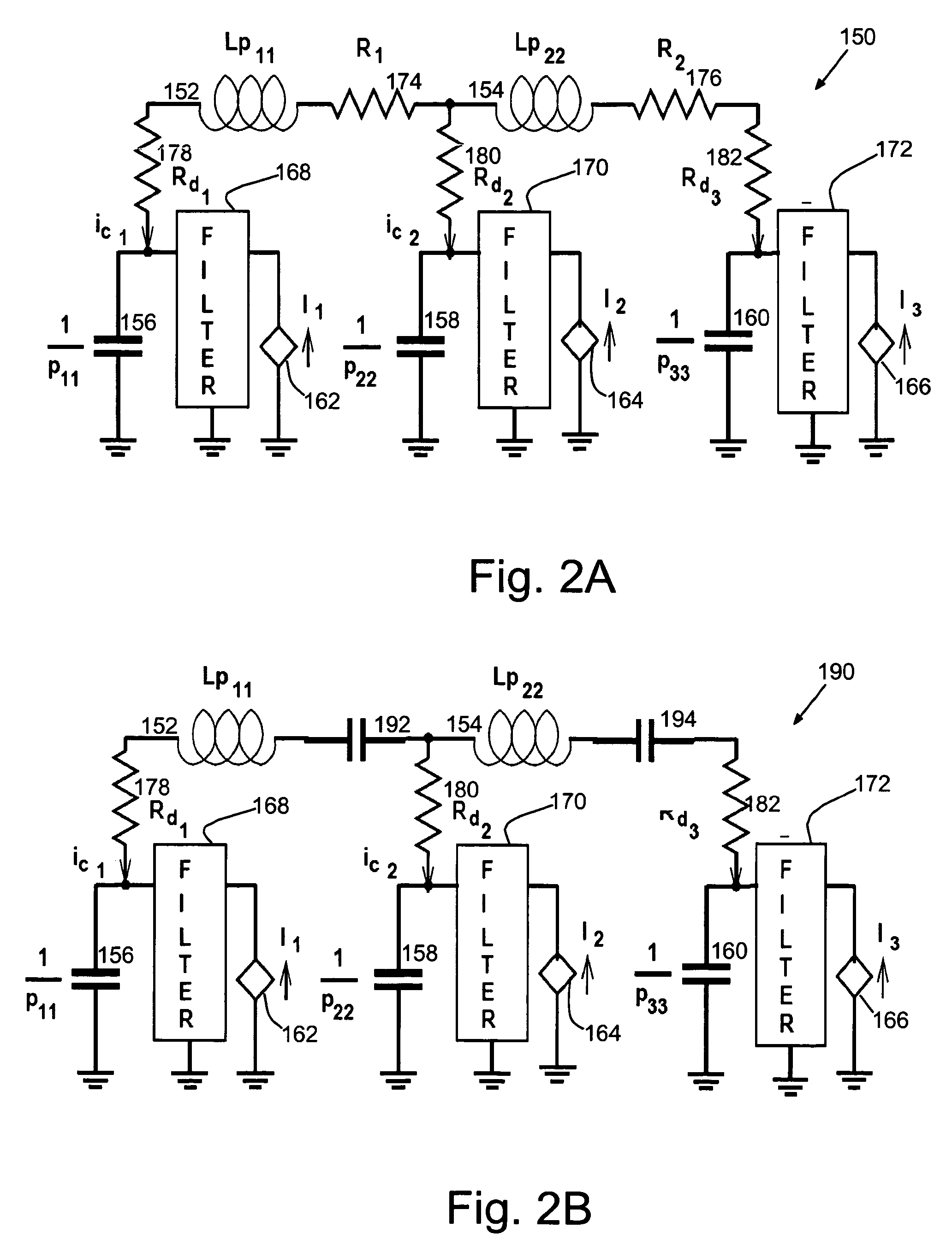
[0016]Turning now to the drawings, and more particularly FIGS. 1A-B show simple prior art electromagnetic response models for modeling electromagnetic effects in a particular medium, i.e., in a conductor or in a dielectric. It should be noted that all circuit models described herein may be transformed to loop equations with and appropriate Norton to Thevenin transformation. The example of FIG. 1A shows a prior network model 100 for modeling electromagnetic effects in an interconnect such as in electronic package wiring, or, an Integrated Circuit (IC) package interconnect. In particular, the network 100 has the general form of the basic Partial Element Equivalent Circuit (PEEC) model for modified nodal analysis (MNA) of a length of a single isolated conductor with distributed (along the length) inductance modeled as partial inductances in series connected inductors 102, 104. Conductor capacitance is modeled as distributed lump capacitances in branch capacitors 106, 108, 110. The bran...


PUM


Abstract

A model for modeling electromagnetic response in a conductor and in dielectric, a method of modeling the electromagnetic response in the conductor and dielectric and a program product therefor. Coupled supplies (delayed capacitive-current-controlled current sources or delayed inductance-voltage-controlled voltage sources) are low pass filtered in an electromagnetic model for the particular medium, e.g., a Partial Element Equivalent Circuit (PEEC) model for a conductor or dielectric. Thus, high frequency model instabilities are substantially reduced or eliminated.

Description

FIELD OF THE INVENTION[0001]The present invention generally relates to modeling electromagnetic effects and more particularly, to modeling electromagnetic effects on circuit interconnects.BACKGROUND DESCRIPTION[0002]Electrical responses in physical structures to electrical forces (e.g., capacitive response to varying voltage or inductive response to varying current) are well known and circuits are easily modeled. Electromagnetic responses in these same physical structures are equally well known, but are much less easily modeled. Thus, electrical circuit analogs are typically used to model electromagnetic responses. One well-known circuit based approach for modeling electromagnetic responses is known as the Partial Element Equivalent Circuit (PEEC) model. A typical PEEC model is numerically equivalent to a full wave method like the method of moments (MoM) solution with Galerkin matching. Simple PEEC models (that do not involve delays) provide an adequate frequency response approximat...

Claims


Application Information

Patent Timeline
Patent Type & Authority Patents(United States)
IPC IPC(8): G06F17/50G01R15/00H02M1/14H03B1/00G01R23/00G05F3/16
CPCG06F17/5036G06F30/367
Inventor RUEHLI, ALBERT E.YANG, CHUANYI
Owner GLOBALFOUNDRIES INC
Learn More