

Injector drive device and injector drive system
a technology of injector drive and drive switch, which is applied in the direction of hybrid vehicles, electrical control, machines/engines, etc., can solve the problems of increasing the heat produced in the power supply unit, and achieve the effect of reducing the size of the drive switch uni
- Summary
- Abstract
- Description
- Claims
- Application Information
AI Technical Summary
Benefits of technology
Problems solved by technology
Method used
Image

Examples
first embodiment
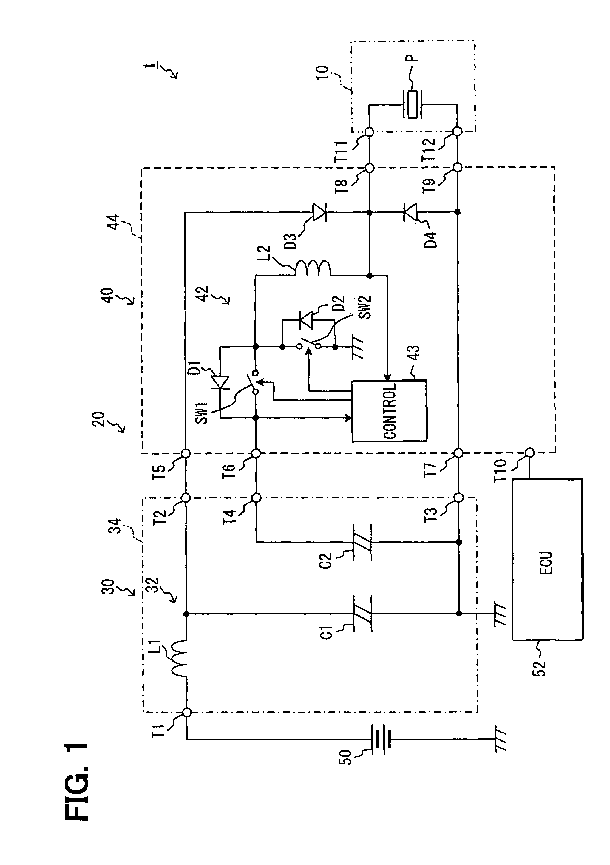
[0016]An injector drive system 1 is mounted in a vehicle that has a diesel engine (not shown) as a vehicle driving source. This injector drive system 1 includes a fuel injector 10 for injecting fuel into the diesel engine, and an injector drive device 20 for driving the injector 10. The injector drive device 20 includes a power supply unit (first power supply unit) 30 that is supplied with power from a battery 50 mounted in the vehicle and generates a voltage higher than the voltage of the battery 50, and an electronic drive unit (EDU) 40.
[0017]In this embodiment, the battery 50 generates a voltage of 12V, and the power supply unit 30 generates a high voltage of tens to hundreds of volt. The power supply unit 30, EDU 40 and battery 50 are placed in an engine compartment in which the diesel engine is housed. The power supply unit 30 is placed externally to the EDU 40, that is, externally to the EDU 40.
[0018]The power supply unit 30 includes a filter 32 constructed of a coil L1 and a ...
second embodiment
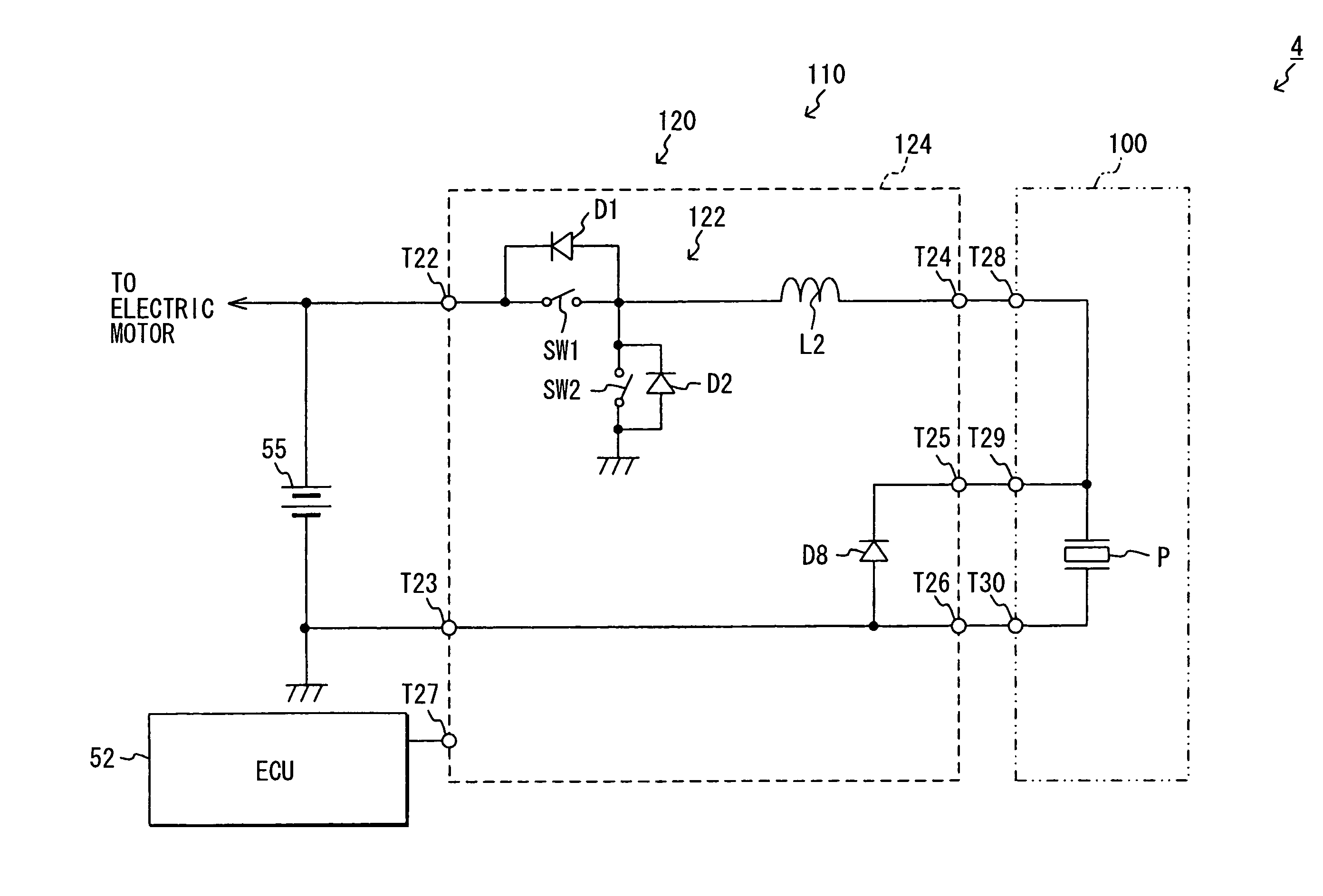
[0030]In the first embodiments power of the battery 50 is supplied directly to the power supply unit 30. In the second embodiment, power of the battery 50 is supplied by the power supply unit 30 through the EDU 40. As shown in FIG. 3, an injector drive system 2 is different from the injector drive system 1 in that the filter 32 is provided in the EDU 40, not in the power supply unit 30.
[0031]One end of the capacitor C1 of the filter 32 is connected to one end of the coil L1 of the filter 32. The other end is connected to the negative pole of the DC-DC capacitor C2, the anode of the diode D4, the end of the piezoelectric element P on the opposite side to the charging / discharging coil L2, and the negative terminal of the battery 50. The other end of the coil L1 of the filter 32 is connected to the positive terminal of the battery 50 through the terminal T5 of the EDU 40. Thus, in the injector drive system 2, power of the battery 50 is supplied by the power supply unit 30 through the i...
third embodiment
[0034]In the first and second embodiments, the EDU 40 is provided for each injector 10. In this third embodiment, one EDU 70 drives multiple (for example, four) injectors 90. As shown in FIG. 4, an injector drive system 3 in this embodiment includes an injector drive device 80 having a power supply unit 60 and an EDU 70 for the injectors 90.
[0035]The power supply unit 60 is placed externally to the EDU 70, that is, externally to its housing 76. The power supply unit 60 includes the filter 32, the DC-DC capacitor C2, a boost coil L3, a diode D5, a boost switch SW3, and a housing 62. In the housing 62 of the power supply unit 60, there are housed the filter 32, DC-DC capacitor C2, boost coil L3, diode D5, and boost switch SW3.
[0036]One end of the coil L1 of the filter 32 is connected to the positive terminal of the battery 50 through a terminal T13 provided on the housing 62, and the other end is connected to one end of the boost coil L3. The other end of the boost coil L3 is connecte...
PUM
 Abstract
Description
Claims
Application Information