Integrated fuel injection and mixing systems for fuel reformers and methods of using the same

a fuel reformer and fuel injection technology, applied in the direction of machines/engines, combustion air/fuel air treatment, combustion gas purification/modification, etc., can solve the problems of high manufacturing cost, state-of-the-art fuel reformers are not yet capable of meeting stringent requirements for commercial or military applications, and achieve the effect of improving mixing and uniformity of feed streams

Active Publication Date: 2009-06-16
COLLINS ENGINE NOZZLES INC
View PDF66 Cites 33 Cited by
  • Summary
  • Abstract
  • Description
  • Claims
  • Application Information

AI Technical Summary

Benefits of technology

[0015]In preferred embodiments, the present invention provides integrated fuel injection and mixing systems comprising a gas-assisted simplex fuel injector, a stabilizing mixer / swirler, and a divergent-convergent mixing chamber. The injection system has the ability to effectively atomize liquid fuels and to achieve complete evaporation and mixing within a short distance at various operating conditions. The mixing chamber introduces a secondary fluid to assist in the mixing operation. Inside the mixing chamber, a flow-stabilizing mixer / swirler is utilized to help confine the spray whirling around the center body and to keep the spray from fluttering or biasing towards one side.
[0016]These components can be properly integrated as a compact unit to meet the various requirements of a fuel reformer. Optionally, the systems also can include mesh screens and / or anti-drooling and anti-carbon spiral grooves in the walls of the mixing chamber. Accordingly, not only do the embodied systems exhibit excellent performance in atomization and mixing, but they also tolerate carbon formation, allowing extended service life.
[0018]The fuel droplets are discharged into a divergent-convergent mixing chamber at high speed where they are thoroughly mixed with the surrounding heated airflow and / or steam flow. Thus, it is another object of the present invention to provide means for and methods of introducing a uniform secondary airflow into the mixing chamber to surround the central fuel spray to prevent fuel droplets from adhering to the chamber walls or accumulating near the corner areas.
[0020]In yet another embodiment, the present invention discloses a mixing chamber that incorporates a stack of mesh screens to further enhance the mixing and uniformity of the feed streams prior to entering the reactor section.
[0021]It is a further object of the present invention to provide a mixing chamber that can tolerate droplet impingement on the wall surfaces and the resulting potential of carbon formation due to fuel accumulation.

Problems solved by technology

In addition to high manufacturing cost, the fuel cell industry is faced with several critical challenges that must be resolved before fuel cell systems can be fully commercialized for wide spread power generation applications.
In short, current, state-of-the-art fuel reformers are not yet capable of meeting the stringent requirements for commercial or military applications.
Particularly, current, state-of-the-art fuel reformers are heavy in weight, large in physical size, and provide only moderate conversion efficiency.
Furthermore, most of the fuel reformers are vulnerable to carbon formation, necessitating either frequent cleaning or high oxygen / carbon (“O / C”) ratios for sustained operation.
Operating at high O / C ratios, however, reduces the overall system efficiency.
Also, the existing catalysts used for the reformers cannot tolerate significant sulfur levels and thus require the liquid fuels to be desulfurized.
Failure to provide a uniform fuel vapor mixture prior to entering the catalytic reactor can result in hot spots and carbon formation.
Moreover, non-uniform gas streams within the mixing chamber and / or catalytic reactor also could lead to significant performance degradation and reduced reformer efficiency.
Finally, the catalytic reactor also may encounter a significant pressure drop due to carbon or soot deposits and build-up, which would necessitate additional pressure or momentum to force the gas streams through the catalytic reactor.

Method used


Image

  • Integrated fuel injection and mixing systems for fuel reformers and methods of using the same
  • Integrated fuel injection and mixing systems for fuel reformers and methods of using the same
  • Integrated fuel injection and mixing systems for fuel reformers and methods of using the same

Examples


first embodiment

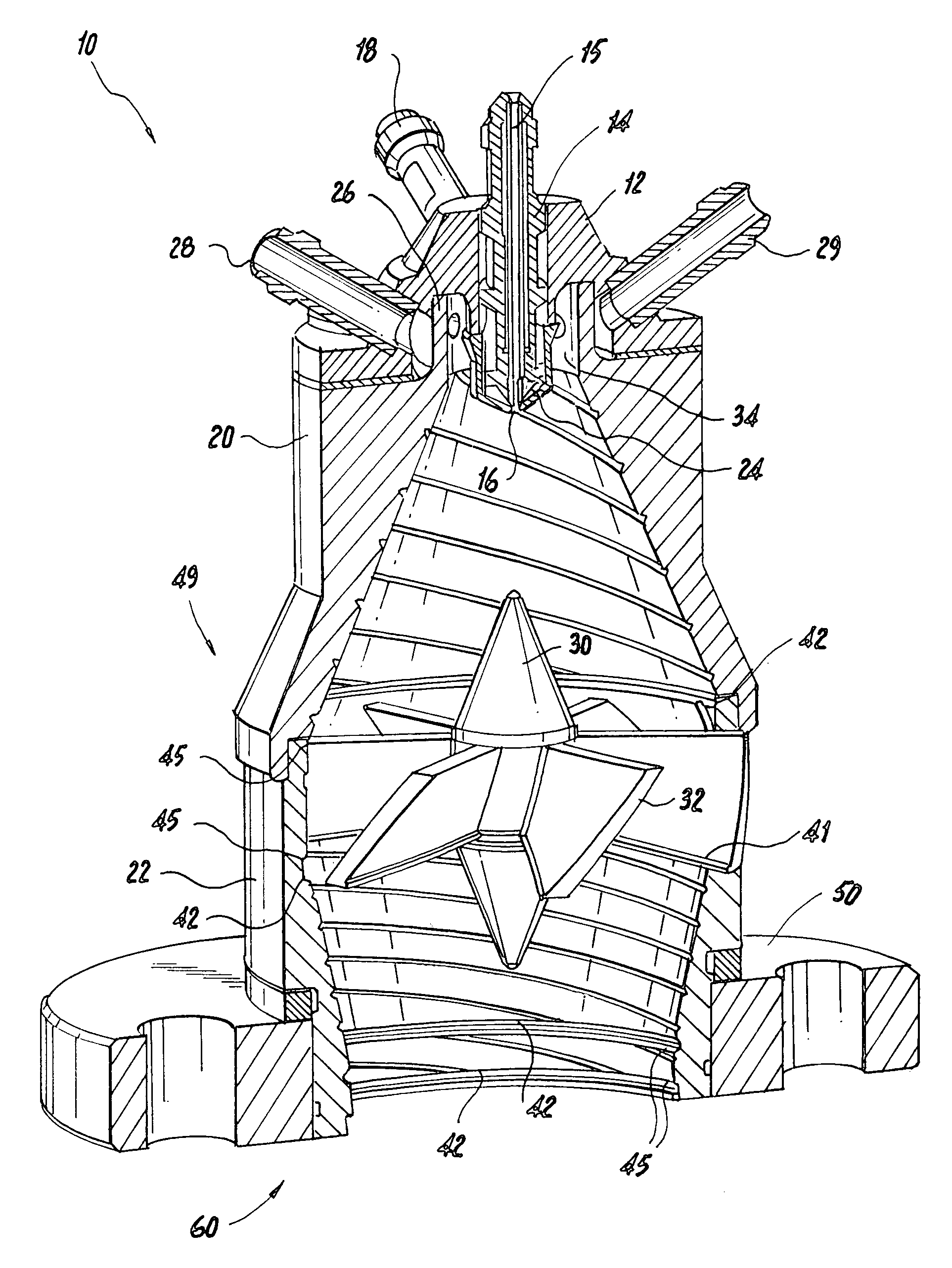
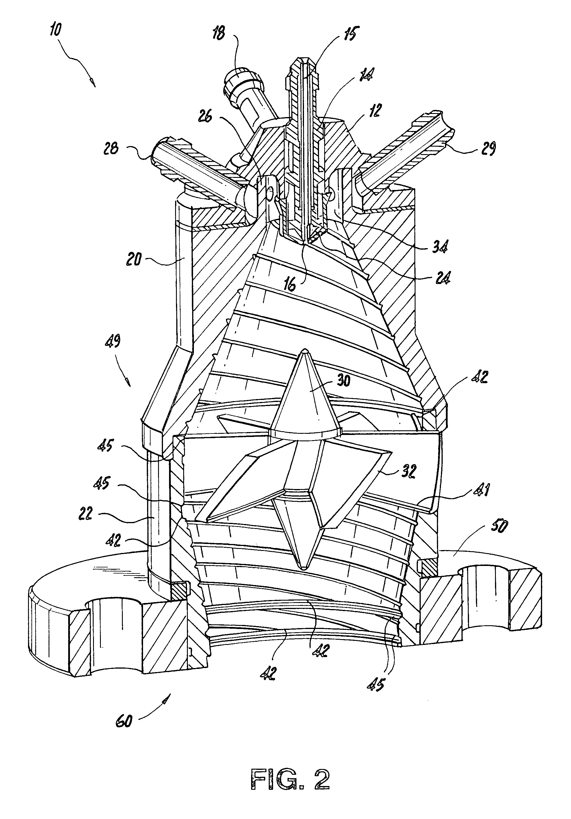
[0039]Having described a conventional fuel reformer 10, we will now describe an integrated fuel injection and mixing system 10 according to the present invention. Referring to FIG. 2, there is shown an integrated fuel injection and mixing system 10 for an auto-thermal-type reformer (“ATR”). Preferably, the embodied injection and mixing system 10 comprises a fuel injector 14 (i.e., an injecting means); a mixing chamber 49 (i.e., a mixing means); and a stabilizing mixer / swirler 30 (i.e., a stabilizing means). The injection system 14 has the ability to atomize liquid hydrocarbon fuels and to achieve complete evaporation and mixing within a short distance at various operating conditions. The mixing chamber 49 introduces a secondary fluid to assist in the mixing operation. Inside the mixing chamber 49, the flow-stabilizing mixer / swirler 30 helps to confine the spray rotating about the center of the mixing chamber 49 to keep the spray from fluttering or biasing towards one side. Furthermo...

second embodiment

[0073]In a second embodiment, the present invention provides an integrated fuel injection and mixing system that is structured and arranged for use with other fuel reformer types. For example, the embodied integrated fuel injection and mixing system can be modified for compatibility with either a steam-type reformer (SR) or a catalytic partial oxidation-type (CPOX) reformer, by providing two feed streams to the injector unit. Moreover, those of ordinary skill in the art will realize that, slight modification can be made to the injector outlet cone 44 described in FIG. 3 for ATR applications to adapt the injection system to meet operational requirements for SR or CPOX reformers.

[0074]For example, FIG. 8 shows an illustrative embodiment of a fuel injector that could be used for the steam-type or catalytic partial oxidation-type reformers. As with the ATR reformer, liquid hydrocarbon fuel can be introduced into the injector 10 through a fuel conduit 15 and an atomizing gas stream 4 can...


PUM

PropertyMeasurementUnit
inlet pressureaaaaaaaaaa
angleaaaaaaaaaa
angleaaaaaaaaaa

Abstract

Systems and methods for injecting and mixing a liquid hydrocarbon fuel to provide a uniform, homogenous fuel vapor mixture for introduction into a fuel reformer for use with a fuel cell are disclosed. Preferably, the system includes a fuel injector that generates and aspirate a liquid fuel in the presence of an atomizing gas stream; a diverging-converging mixing chamber, into which the atomized fuel and a secondary fluid stream are introduced, to enhance the mixing of the fuel and the added heated gas or steam; and a mixer / swirler, which can be centrally located in the mixing chamber between the upper and lower chambers, to stabilize the fuel vapor mixture further for greater uniformity and homogeneity. More preferably, grooves and / or brazed wires can be provided on the surfaces of the mixing chamber and / or mixer / swirler to channel any accumulated fuel so as to provide sufficient time to evaporate the accumulated fuel.

Description

FIELD OF THE INVENTION[0001]The present invention relates to fuel injection and mixing systems and related methods of mixing fuel and, more particularly, to integrated fuel injection and mixing systems for use with fuel reformers to generate hydrogen-rich gas for use in fuel cells and related methods of mixing fuel.BACKGROUND OF THE INVENTION[0002]Fuel cells are alternative energy producing systems that generate electricity from common fuel sources such as natural gas and that, typically, have higher efficiencies and lower emissions than conventional systems. More specifically, fuel cells are electro-mechanical devices that provide electrical power by reacting, for example, hydrogen gas (H2) usually in the form of natural gas or ethanol with an oxidant, e.g., air or oxygen gas (O2). The gases react to produce electrical current and a relatively harmless water bi-product.[0003]For example, a fuel, e.g., hydrogen gas (H2), can be introduced at a first electrode (an anode), where a cat...

Claims


Application Information

Patent Timeline
Patent Type & Authority Patents(United States)
IPC IPC(8): F02M29/06
CPCB01F3/04049B01F5/0451B01F5/0618B01J4/002B01J19/26C01B3/38F02M25/12F02M27/02H01M8/0618B01F2005/0636B01F2005/0637C01B2203/0233C01B2203/0261C01B2203/066C01B2203/1276C01B2203/1288H01M2008/1293Y02T10/121Y02E60/50Y02E60/525Y10S261/55Y02T10/12B01F23/2132B01F25/3131B01F25/4316B01F25/431971B01F25/431972
Inventor MAO, CHIEN-PEISHORT, JOHN
Owner COLLINS ENGINE NOZZLES INC
Why Eureka
Try Eureka