Compact high efficiency gasifier

a gasifier, high-efficiency technology, applied in the field of gasifiers, can solve the problems of gasifier thermal efficiency, gasifier volume and capital cost being much higher than necessary, and gasifier thermal efficiency not being effective, so as to achieve the effect of ‘free floating’

Active Publication Date: 2009-06-16
THE BOEING CO +1
View PDF27 Cites 53 Cited by
  • Summary
  • Abstract
  • Description
  • Claims
  • Application Information

AI Technical Summary

Benefits of technology

[0004]In one preferred embodiment, the present invention provides a compact, highly efficient gasifier system for converting a carbonaceous material into a gaseous product. The gasifier system includes a gasification chamber spool that has a ceramic matrix composite (CMC) liner effectively ‘free floating’ within the gasification chamber spool. The CMC liner is adapted to form a solidified slag protective layer on an interior surface of the liner from molten slag flowing through the gasification chamber spool. The gasifier system additionally includes a convergent spool coupled to the gasification chamber spool that also includes a CMC liner adapted to form a solidified slag protective layer on an interior surface of the liner from molten slag flowing through the convergent spool.

Problems solved by technology

However, these entrained flow gasifiers fail to make use of rapid mix injector technology with regeneratively cooled hardware.
The failure to use such technologies causes gasifier volumes and capital costs to be much higher than necessary, and gasifier thermal efficiencies, i.e. cold gas efficiencies (CGE), to be much lower than theoretically possible.

Method used


Image

  • Compact high efficiency gasifier
  • Compact high efficiency gasifier
  • Compact high efficiency gasifier

Examples


Embodiment Construction

[0019]The following description of the preferred embodiments is merely exemplary in nature and is in no way intended to limit the invention, its application or uses. Additionally, the advantages provided by the preferred embodiments, as described below, are exemplary in nature and not all preferred embodiments provide the same advantages or the same degree of advantages.

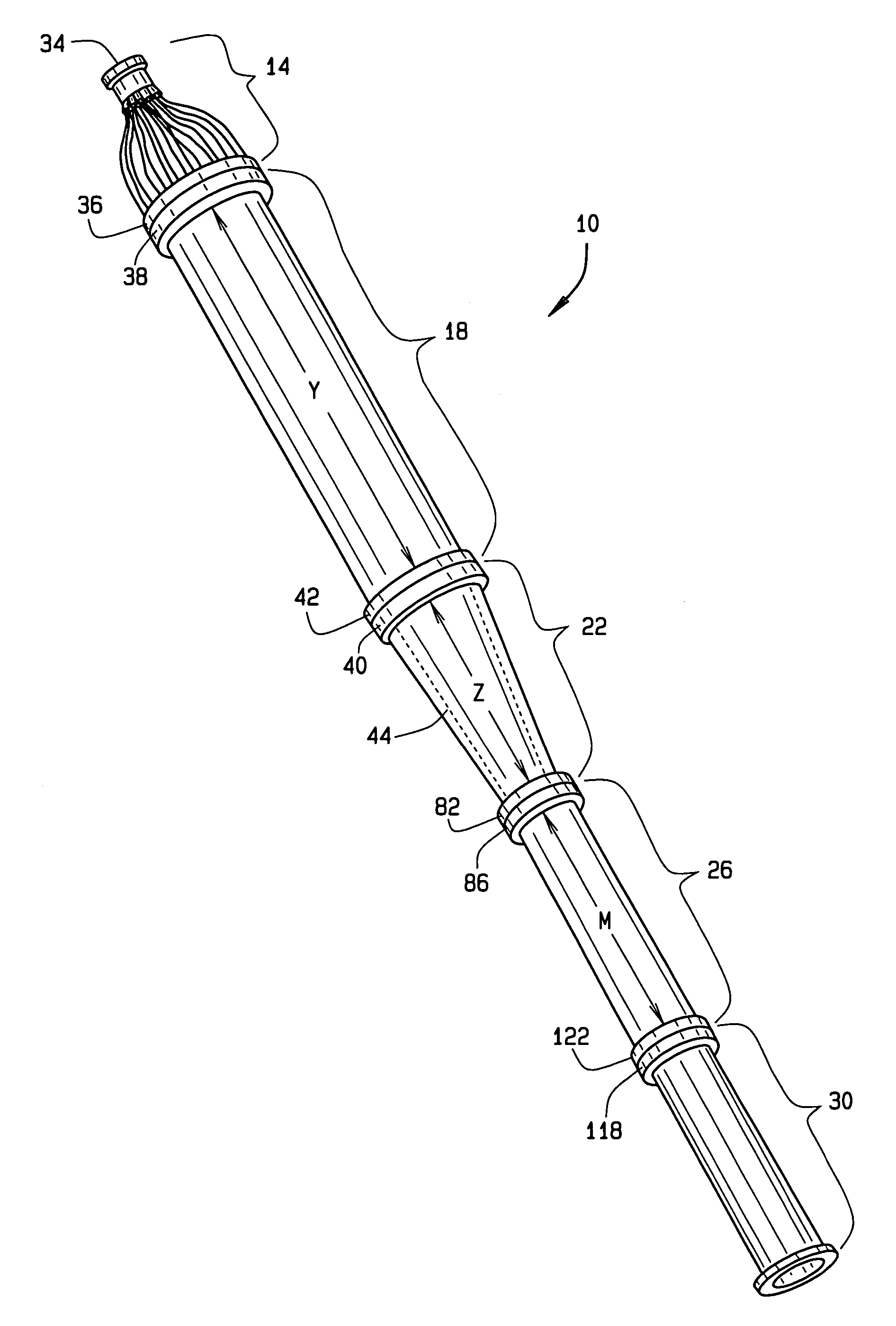
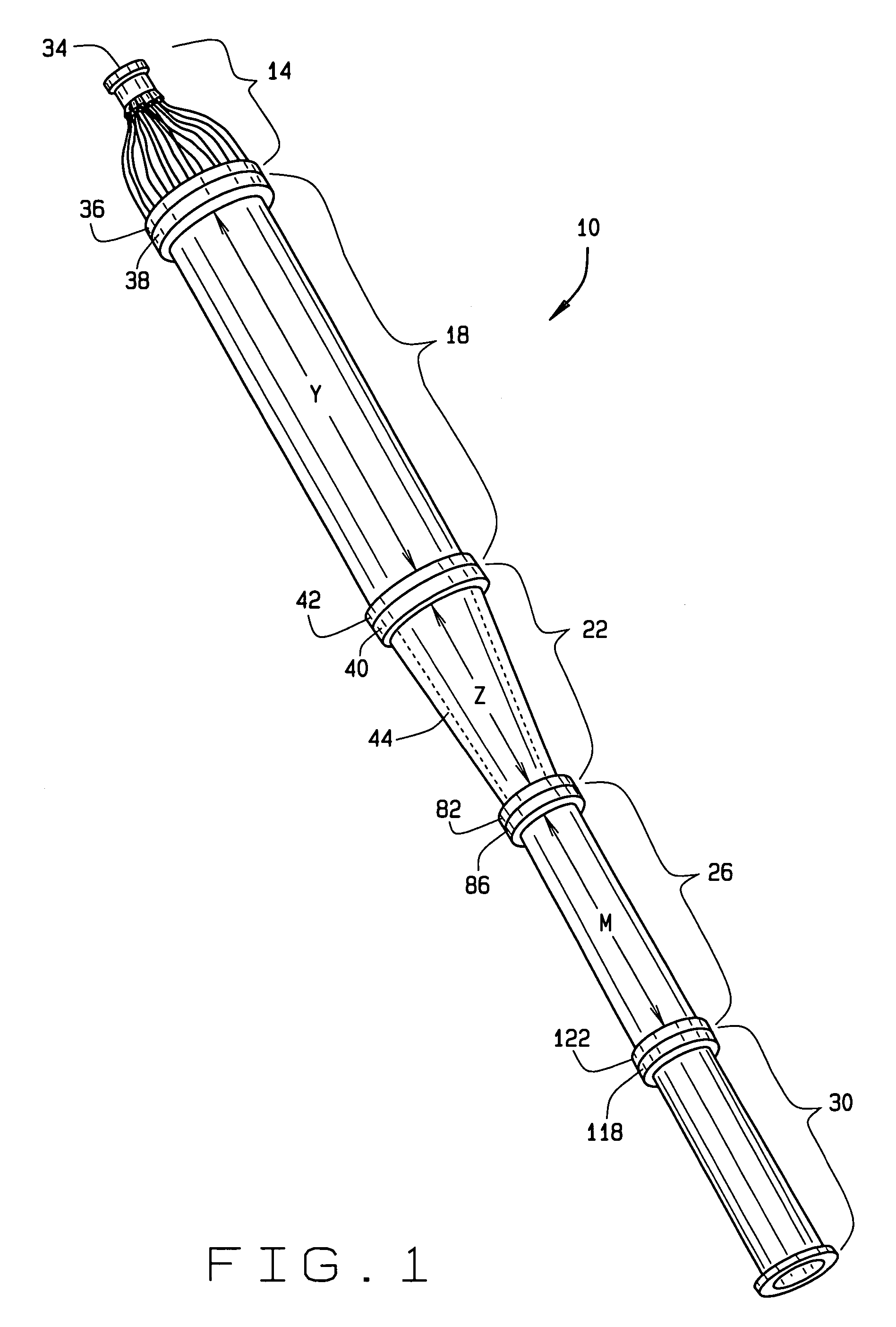
[0020]FIG. 1 is an illustration of a compact, highly efficient single stage gasifier system 10 capable of producing a syngas from a carbonaceous material such as coal or petcoke with a cold gas efficiency (CGE) greater than 80%, in accordance with one preferred embodiment of the present invention. The gasifier system 10 includes an injector spool 14 coupled to a gasification chamber spool 18 that is coupled to a convergent spool 22. The convergent spool 22 is coupled to a heat exchanger (HEX) quench spool 26. In one preferred embodiment, the HEX quench spool 26 is coupled to a deluge quench spool 30. The injector spo...


PUM

PropertyMeasurementUnit
diameteraaaaaaaaaa
diameteraaaaaaaaaa
diameteraaaaaaaaaa

Abstract

A gasifier system is provided that includes a gasification chamber spool that has a ceramic matrix composite (CMC) liner adapted to form a solidified slag protective layer on an interior surface of the liner from molten slag flowing through the gasification chamber spool. The gasification system additionally includes a heat exchanger (HEX) quench spool that also includes a CMC liner adapted to form a solidified slag protective layer on an interior surface of the liner from molten slag flowing through the HEX quench spool. Additionally, the HEX quench spool includes a parallel plate HEX core having a plurality of CMC panels. The CMC panels are adapted to form a solidified slag protective layer on exterior surfaces of each respective CMC panel from molten slag flowing through the HEX quench spool. Furthermore, each CMC panel includes a plurality of internal coolant channels adapted to exchange sensible waste heat from the hot product flowing through the HEX quench spool with a coolant flowing through the internal coolant channels. The sensible waste heat absorbed by the coolant is recovered by the gasification system by utilizing the heated coolant in various operational phases of the gasification system.

Description

FIELD OF INVENTION[0001]The invention relates generally to gasifiers for converting a coal precursor, such as coal or petcock, into a synthetic gas. More particularly, the invention relates to a compact, highly efficient single stage gasifier.BACKGROUND OF THE INVENTION[0002]Electricity and electrically powered systems are becoming ubiquitous and it is becoming increasingly desirable to find sources of power. For example, various systems may convert various petrochemical compounds, such as coal and petcoke, into electrical energy. Further, such petrochemical compounds are used to create various other materials such as steam that are used to drive steam powered turbines.[0003]The gasification of coal and petcoke to synthesis gas (syngas), e.g. mixtures of hydrogen and carbon monoxide, is a well-known industrial process used in the petrochemical and gas power turbine industries. Over the last 20 years, the use of entrained flow coal gasifiers has become a very common process in the pr...

Claims


Application Information

Patent Timeline
Patent Type & Authority Patents(United States)
IPC IPC(8): B01J19/00
CPCC10J3/485C10J2200/09C10J2300/093C10J2300/1823C10J2300/0959C10J2300/0969C10J2300/0973C10J2300/0943Y02P20/129
Inventor SPROUSE, KENNETH MFARHANGI, SHAHRAMMATTHEWS, DAVID R
Owner THE BOEING CO
Why Eureka
Try Eureka