Spacer grid with mixing vanes and nuclear fuel assembly employing the same

a spacer grid and nuclear fuel technology, applied in nuclear engineering problems, nuclear elements, greenhouse gas reduction, etc., can solve the problems of reducing the output power of the fuel rod, limiting the way of conventional mixing vanes, and affecting the thermal performance of the fuel assembly, so as to promote optimized even and sustained interchannel mixing, effectively mix coolant, and deflect coolant flow

Inactive Publication Date: 2009-06-16
WESTINGHOUSE ELECTRIC CORP
View PDF25 Cites 29 Cited by
  • Summary
  • Abstract
  • Description
  • Claims
  • Application Information

AI Technical Summary

Benefits of technology

[0009]An object of the present invention is to provide a mixing vane that is tunable in order to affect (i.e., control or adjust) and thus optimize for the particular application at hand the coolant flow pattern that is formed, rather than merely deflecting the coolant flow.
[0010]Another object of the present invention is to provide a mixing vane that promotes optimized even and sustained interchannel mixing.
[0011]Yet another object of the present invention is to provide a mixing vane that more effectively mixes coolant as it moves upwards through the fuel assembly, thereby mitigating regions of varying coolant temperature.
[0012]A further object of the present invention is to provide mixing vane that is easily manufactured using conventional die technology.
[0013]Another object of the present invention is to provide a mixing vane with an upper piece, a lower piece, and a middle ligament, that are easily tuned or adjusted by bending, rotating, and twisting, in order to optimize the coolant flow.

Problems solved by technology

At locations adjacent to the fuel rods, the coolant may be partially overheated, which can adversely affect the thermal performance of the fuel assembly and reduce the output power of the fuel rods.
Conventional mixing vanes, however, tend to be restricted in the ways in which they deflect the flow of coolant as it moves upwards through the fuel assembly.
They do not provide a robust means for adjusting or tuning the vanes in order to optimize the flow pattern that is formed.
As a result, conventional mixing vanes cannot effectively achieve the most desirable type of coolant flow—even and sustained mixing—for the particular application at hand.

Method used


Image

  • Spacer grid with mixing vanes and nuclear fuel assembly employing the same
  • Spacer grid with mixing vanes and nuclear fuel assembly employing the same
  • Spacer grid with mixing vanes and nuclear fuel assembly employing the same

Examples


Embodiment Construction

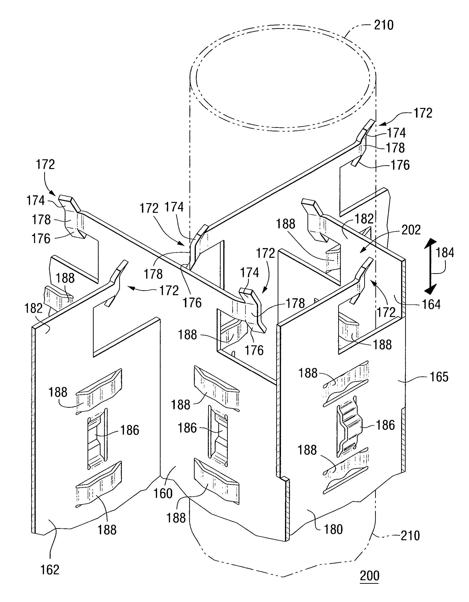
[0025]The description contained herein primarily refers to the use of a mixing vane having a generally rectangular shape. It will, however, be appreciated the mixing vanes may have any suitable shape, size, or dimensions. It will also be appreciated that although each mixing vane is contemplated as being formed from the grid strap material and connected to the grid strap as an integral component, that the mixing vanes could also be connected by welding, brazing, or mechanically securing them to the grid straps. The mixing vanes can also be made from any known or suitable material (e.g., without limitation zirconium alloy or nickel-steel alloy). It will further be appreciated that the Figures provided herein are provided for simplicity of illustration of only certain examples or variations of mixing vanes in accordance with the invention, and are not meant to be limiting upon the scope of the invention. It will also be appreciated that the Figures and, in particular, certain features...


PUM


Abstract

A spacer grid having tunable mixing vanes for optimizing coolant flow is provided for a nuclear fuel assembly. The mixing vanes include an upper piece and a lower piece, which are coupled to a middle ligament that is coupled to the top or downstream portion of one or more of the grid straps forming the spacer grid. The upper piece, lower piece, and middle ligament are bent, rotated, and / or twisted into various positions to more effectively mix the coolant and affect the coolant's flow as it moves upwards through the fuel assembly. For example, in one embodiment, the mixing vane has an “S” shape wherein the middle ligament is positioned parallel to the longitudinal axes of the fuel rods of the fuel assembly, the upper piece bends towards one of the fuel rods, and the lower piece bends away from the fuel rod. In this manner, optimized even and sustained mixing of the coolant is provided.

Description

FIELD OF THE INVENTION[0001]The present invention relates generally to nuclear reactors and, more particularly, to spacer grids for a nuclear fuel assembly, including mixing vanes to effectively mix coolant as it flows through the fuel assembly.BACKGROUND INFORMATION[0002]Nuclear fuel assemblies for light water nuclear reactors, such as, for example, pressurized water reactors (PWRs) and boiling water reactors (BWRs), generally include a plurality of fuel rods with circular cross-sections that are arranged parallel to one another at regularly or irregularly spaced intervals. Each fuel rod comprises a stack of fuel pellets (e.g., uranium oxide pellets) surrounded with cladding that is made from zirconium alloy or other suitable material. The fuel rods are held at the spaced intervals with respect to one another by one or more spacer grids. Each spacer grid includes a plurality of interlocking grid straps that are welded together to form an array of four-walled cells in an “egg-crate”...

Claims


Application Information

Patent Timeline
Patent Type & Authority Patents(United States)
IPC IPC(8): G21C3/34
CPCG21C3/322G21C3/352G21Y2002/304G21Y2004/30G21Y2004/403Y02E30/38Y02E30/30
Inventor SMITH, III, LEVIE D.MARZEAN, MICHAEL A.
Owner WESTINGHOUSE ELECTRIC CORP
Why Eureka
Try Eureka