System for monitoring bearing wear

a technology for bearing wear and monitoring system, which is applied in the direction of mechanical equipment, instruments, transportation and packaging, etc., can solve the problems of substantially and achieve the effect of reducing the wear rate of optical fibers

Inactive Publication Date: 2009-06-23
ROCKWELL AUTOMATION TECH
View PDF45 Cites 30 Cited by
  • Summary
  • Abstract
  • Description
  • Claims
  • Application Information

AI Technical Summary

Benefits of technology

[0039]A system for controlling pressure of a seal against a contact surface is provided. The system comprises at least one optical fiber embedded in a seal, the at least one optical fiber being adapted to transmit light from a light source, a measuring system operatively coupled to the optical fiber, the optical fiber providing the measuring system with information relating to at least one condition of th

Problems solved by technology

Since the optical fiber is substantially weaker than the article it is disposed in,

Method used


Image

  • System for monitoring bearing wear
  • System for monitoring bearing wear
  • System for monitoring bearing wear

Examples


Embodiment Construction

[0070]The present invention will now be described with reference to the drawings, wherein like reference numerals are used to refer to like elements throughout.

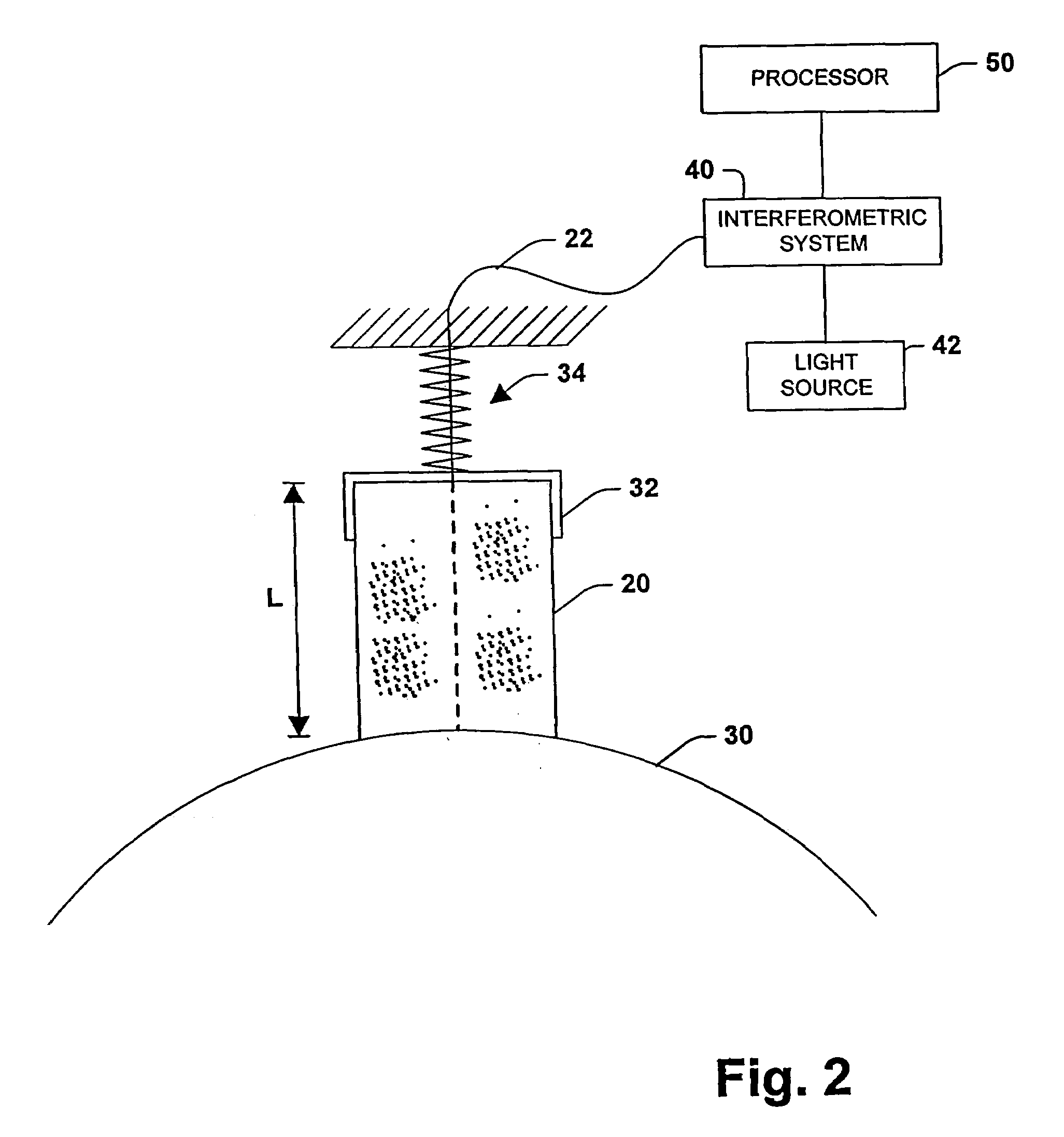
[0071]As is mentioned above, the present invention employs an optical fiber to provide data relating to an article the fiber is embedded in or data relating to an environment the fiber is exposed to. Such data includes the amount of wear and the rate of wear of the article. Furthermore, the present invention can provide data relating to surface condition assessment, article temperature and / or environment temperature, motor speed, and article pressure and / or environmental pressure.

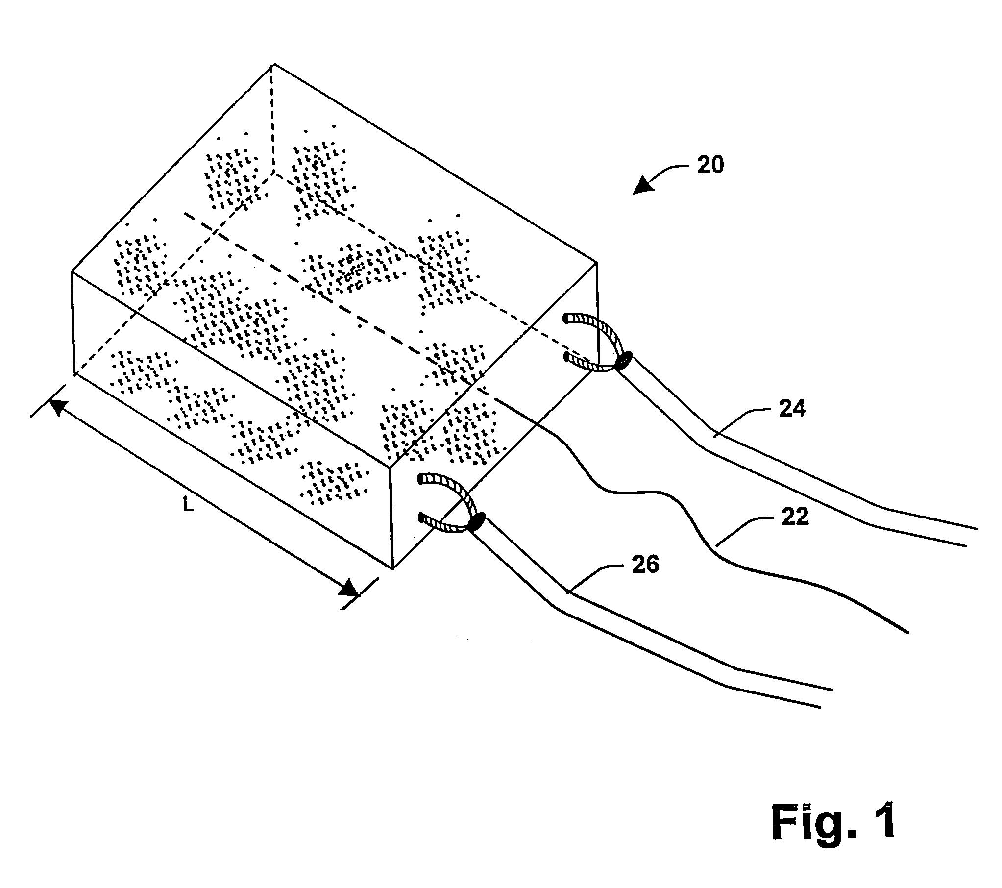
[0072]Referring initially to FIG. 1, a carbon brush 20 is shown in perspective view with an optical fiber 22 embedded therein. Two current carrying conductors 24, 26 are shown fixed to a non-contacting end of the carbon brush. The other end of the carbon brush 20 slidably contacts with another surface (e.g., commutator surface) which is not shown. Th...


PUM


Abstract

A system for determining at least one condition of a bearing including an optical fiber for transmitting light from a light source. The optical fiber is embedded in the bearing and operatively coupled to an interferometric system. The interferometric system is operatively coupled to a processor. The interferometric system provides the processor with information relating to wear of the optical fiber, and the processor determines wear of the bearing, rate of wear and remaining useful life of the bearing based on the information relating to wear of the optical fiber.

Description

CROSS REFERENCE TO RELATED APPLICATIONS[0001]This application is a continuation-in-part (CIP) application of U.S. patent application Ser. No. 09 / 504,440 filed Feb. 16, 2000, now U.S. Pat. No. 6,359,690 entitled APPARATUS, SYSTEM AND METHOD FOR DETERMINING WEAR OF AN ARTICLE, which is a continuation of U.S. patent application Ser. No. 09 / 253,785 filed Feb. 22, 1999 entitled SYSTEM FOR DETERMINING WEAR OF AN ARTICLE (which issued as U.S. Pat. No. 6,067,159), which is a continuation of U.S. patent application Ser. No. 08 / 959,610 filed Oct. 28, 1997 now U.S. Pat. No. 6,111,643 entitled APPARATUS, SYSTEM AND METHOD FOR DETERMINING WEAR OF AN ARTICLE.TECHNICAL FIELD[0002]The present invention generally relates to an apparatus, system and method for determining wear and the rate of wear of an article such as for example a seal, a bearing, a carbon brush, a brake pad or tire.BACKGROUND OF THE INVENTION[0003]Dynamoelectric machines such as direct current (DC) motors use carbon brushes to pro...

Claims


Application Information

Patent Timeline
IPC IPC(8): G01B9/02
CPCB60C11/24B60C23/0408G01B11/06G01M13/04G01D5/35325B60C11/246G01B9/02027G01B9/02023H01R39/36H01R39/26H02K11/35H02K5/14H02K11/25F16J15/3296F16J15/3492
Inventor DISCENZO, FREDERICK M.
Owner ROCKWELL AUTOMATION TECH
Why Eureka
Try Eureka