Probe and optical tomography system

a technology of optical tomography and probe, which is applied in the field of optical probes, can solve the problems of deteriorating resolution, affecting the accuracy of signals, so as to suppress the stress change, prevent the leakage of liquid from the outer envelope of the probe, and increase the heat capacity

Inactive Publication Date: 2009-06-23
FUJIFILM CORP
View PDF5 Cites 5 Cited by
  • Summary
  • Abstract
  • Description
  • Claims
  • Application Information

AI Technical Summary

Benefits of technology

[0012]In view of the foregoing observations and description, the primary object of the present invention is to provide an optical probe which can suppress deterioration in measuring accuracy due to a stress change or a temperature fluctuation because of a local pressure change or a local bending.
[0031]When gas or liquid having a high transmittance to the wavelength of the light is filled in the optical-path-area, the liquid layer does not affect the light led through the optical-path-area, whereby the material of the liquid layer may have a larger heat capacity and may more suppress the stress change.
[0032]When the partition member closely confines the optical fiber and the liquid layer is formed by filling liquid in the partition member, leak of liquid from the probe outer envelope can be surely prevented.
[0033]In accordance with an optical probe and an optical tomography system employing the optical probe, since the optical probe comprises a tubular outer envelope, an optical fiber which is disposed in the direction of axis of the outer envelope inside the outer envelope, a light projecting means which collects light emitted from the front end of the optical fiber and projects it on a body-to-be-scanned disposed externally of the outer envelope, and a partition member which partitions the space between the outer envelope and the optical fiber and between the outer envelope and the light projecting means into an optical-path-area including the optical path of the light emanating from the light projecting means, and a non-optical-path-area and a liquid layer is formed in the non-optical-path-area, when the optical probe is inserted into a living organization and a local pressure, stress change and temperature change, due to bending are applied to the optical probe, the influence on the optical fiber in the probe outer envelope can be suppressed by the pressure in the partition member, and the measuring accuracy can be prevented from deteriorating.
[0034]When an optical fiber holding portion for holding the optical member is provided between the outer envelope and the fiber, the optical fiber is prevented from adhering to the inner surface of the probe outer envelope and application of localized pressure to the optical fiber is avoided, whereby the measuring accuracy can be prevented from deteriorating.
[0035]Further, when a temperature regulator which regulates the temperature of the liquid to be substantially constant is further provided, change of the optical path length in the optical fiber can be prevented, whereby the measuring accuracy can be prevented from deteriorating.

Problems solved by technology

When an optical probe such as disclosed in Japanese Unexamined Patent Publication No. 4(1992)-135550 is inserted into an organic body, a stress change or a temperature fluctuation due to a local pressure change or a local bending of the optical fiber cannot be avoided.
Specifically, in the SS-OCT system, since the optical path length of one light shifts and the phase of the light shifts while the wavelength of the light source is scanned, the place shifted from the original place is observed after Fourier transform is observed, which deteriorates the resolution.
Further, in the SD-OCT system, where the signals are integrally obtained, if the optical path length changes in a time shorter than the time for which the shutter is opened, there gives rise to a problem that the signals are averaged and the S / N ratio of the signal deteriorates.

Method used


Image

  • Probe and optical tomography system
  • Probe and optical tomography system
  • Probe and optical tomography system

Examples


Embodiment Construction

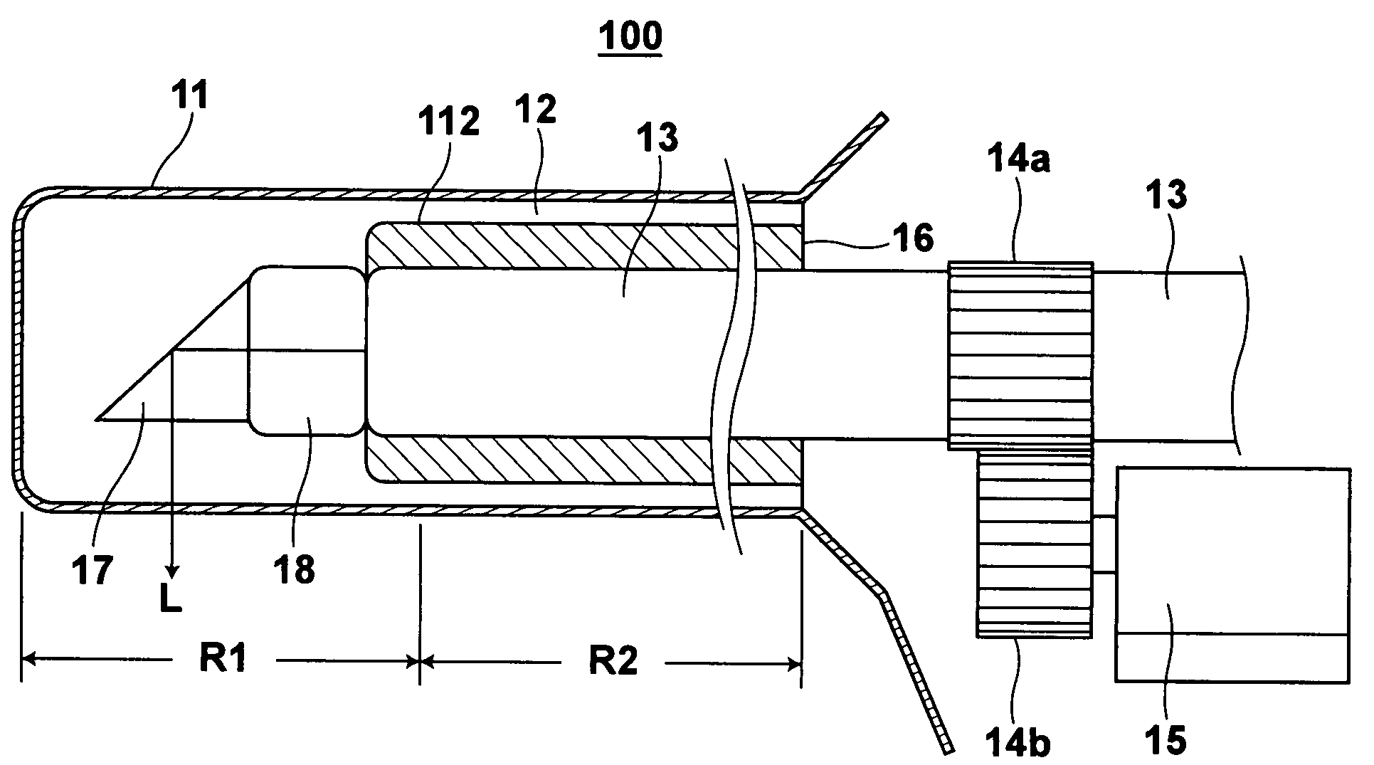
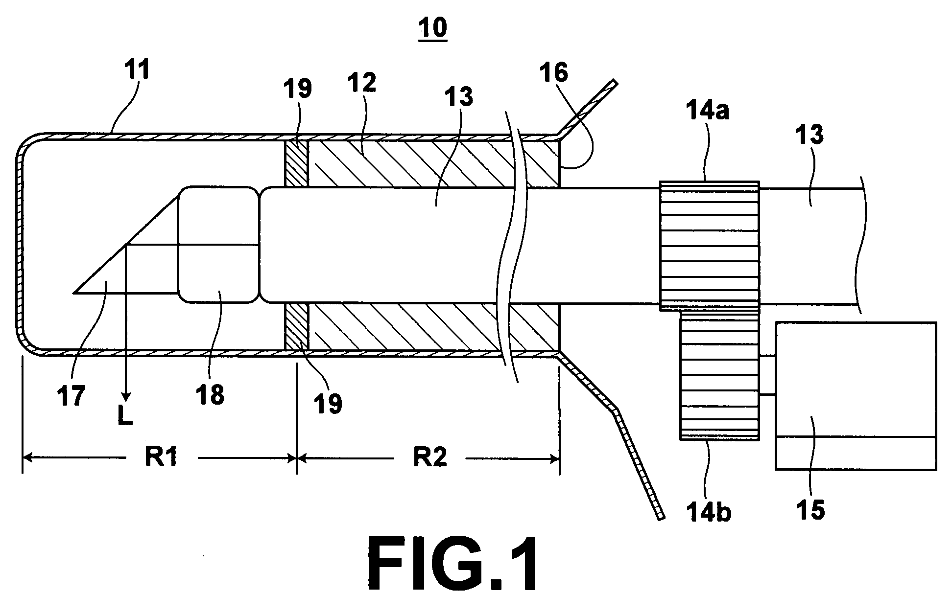
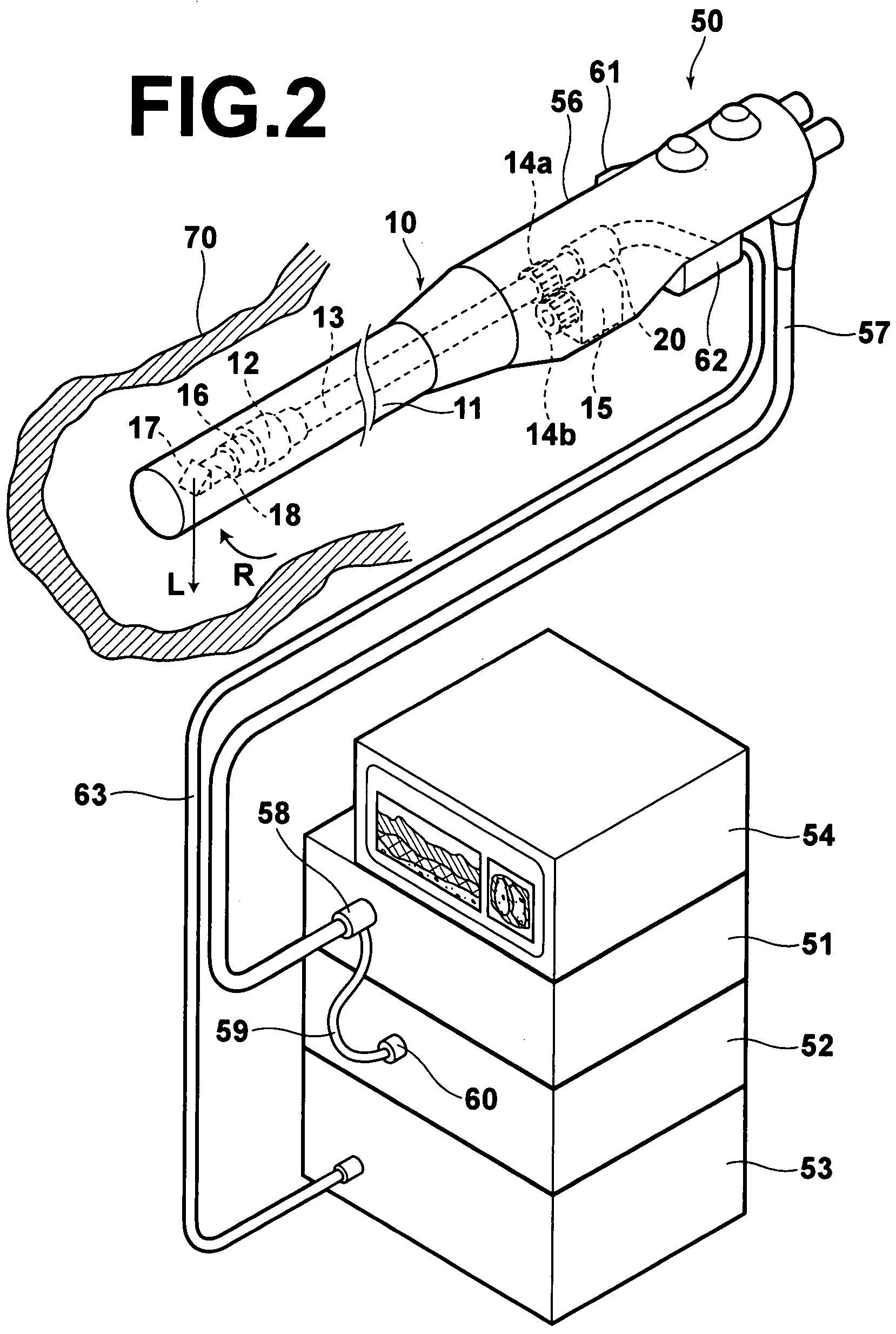
[0045]Embodiments of the present invention will be described in detail with reference to the drawings, hereinbelow. FIG. 1 shows a side shape partly cut-away of an optical probe 10 in accordance with a first embodiment of the present invention. The optical fiber 10, for example, forms a front end portion of an endoscope which forms a part of an optical tomography system. FIG. 2 shows an overall shape of the optical tomography system.

[0046]The optical tomography system will be first described in brief with reference to FIG. 2. The system comprises an endoscope 50 including the optical probe 10; a light source unit 51, a video processor 52, and an optical tomographic processing system 53 to which the endoscope 50 is connected; and a monitor 54 connected to the video processor 52. The endoscope 50 comprises an outer envelope 11 which is flexible and elongated, a control portion 56 connected to the rear end of the endoscope outer envelope 11 and a universal code 57 which extends outward...


PUM


Abstract

An optical fiber is disposed in the direction of axis of the outer envelope inside a tubular outer envelope. Light emitted from the front end of the optical fiber is collected and projected on a body-to-be-scanned disposed externally of the outer envelope, and converged on the body-to-be-scanned. The outer envelope is filled with liquid so that the optical fiber is in the liquid.

Description

BACKGROUND OF THE INVENTION[0001]1. Field of the Invention[0002]This invention relates to an optical probe, and more particularly to an optical probe having a tubular outer envelope and having a function of emitting light from the peripheral surface thereof and an optical tomography system where such an optical probe is employed.[0003]2. Description of the Related Art[0004]As a conventional method for obtaining tomographic images of measurement targets, such as living tissue, a method that obtains optical tomographic images by OCT (Optical Coherence Tomography) measurement has been proposed (refer to Japanese Unexamined Patent Publication Nos. 6(1994)-165784 and 2003-139688). The OCT measurement is a type of light interference measurement method that utilizes the fact that light interference is detected only when the optical path lengths of divided light beams, that is, a measurement light beam and a reference light beam, match within a range of coherence length of a light source. T...

Claims


Application Information

Patent Timeline
Patent Type & Authority Patents(United States)
IPC IPC(8): G02B6/26G01B11/02G02B6/34
CPCA61B5/0066A61B5/6852
Inventor TERAMURA, YUICHI
Owner FUJIFILM CORP
Why Eureka
Try Eureka