Coating treatment apparatus and coating treatment method

a technology of coating treatment and treatment apparatus, which is applied in the direction of coatings, pretreated surfaces, basic electric elements, etc., can solve the problems of increasing the number of units, complex process steps, and requiring a lot of effort to change work, and achieve the effect of suppressing the evaporation rate of coating solution

Inactive Publication Date: 2009-06-30
TOKYO ELECTRON LTD
View PDF8 Cites 8 Cited by
  • Summary
  • Abstract
  • Description
  • Claims
  • Application Information

AI Technical Summary

Benefits of technology

[0012]In recent years, manufacture of the mask substrate by coating and development is shifting from the conventional production model of fewer varieties and higher volume to the production model of more varieties and lower volume. If a gas flow restraining ring with an appropriate inside diameter is prepared for each kind of product so that the gas flow restraining ring is changed in accordance with the kind of product in a common unit, that changing work may require much effort. Further, if a dedicated coating unit is prepared for each kind of product, it may increase the number of units and make the process steps complicated.
[0025]According to the present invention, the gas flow restraining ring is provided to freely rise and lower, so that, for example, even when substrates with different coating conditions are treated, the gas flow hits against the front face at the corner portions of the substrate can be controlled by appropriately setting the height position of the gas flow restraining ring. This suppresses the evaporation rate of the coating solution applied on the front face at the corner portions of the substrate to thereby enable the evaporation rate of the solvent to be uniform within the plane of the substrate. Therefore, it can be restrained that the coating solution existing on the surface at the corner portions of the substrate dries faster and becomes thicker than that existing inside them, and as a result a coating film uniform within the plane can be formed on the front face of the substrate. Accordingly, it is unnecessary to replace the gas flow restraining ring with another.

Problems solved by technology

However, there has been a problem as follows.
The problem is that the inside diameter of the gas flow restraining ring sensitively affects the film thickness profile of the coating film such that the way of the film rising up at the corner portions changes due to, for example, a change of only 1 mm in the inside diameter of the gas flow restraining ring, and therefore when the coating condition such as the kind of coating solution, a target value of a film thickness, a region on the substrate where a predetermined in-plane uniformity needs to be secured, or the like is changed, a gas flow restraining ring having an appropriate inside diameter needs to be prepared in accordance with the change.
If a gas flow restraining ring with an appropriate inside diameter is prepared for each kind of product so that the gas flow restraining ring is changed in accordance with the kind of product in a common unit, that changing work may require much effort.
Further, if a dedicated coating unit is prepared for each kind of product, it may increase the number of units and make the process steps complicated.
However, if the rotation speed is increased, the difference in speed between the corner portions and the inner region becomes large and the difference in drying rate of the solvent accordingly increases, and as a result, there is a fear that the difference in the film thickness of the coating film is further increased between the corner portions and the inner region of the substrate.

Method used


Image

  • Coating treatment apparatus and coating treatment method
  • Coating treatment apparatus and coating treatment method
  • Coating treatment apparatus and coating treatment method

Examples


Embodiment Construction

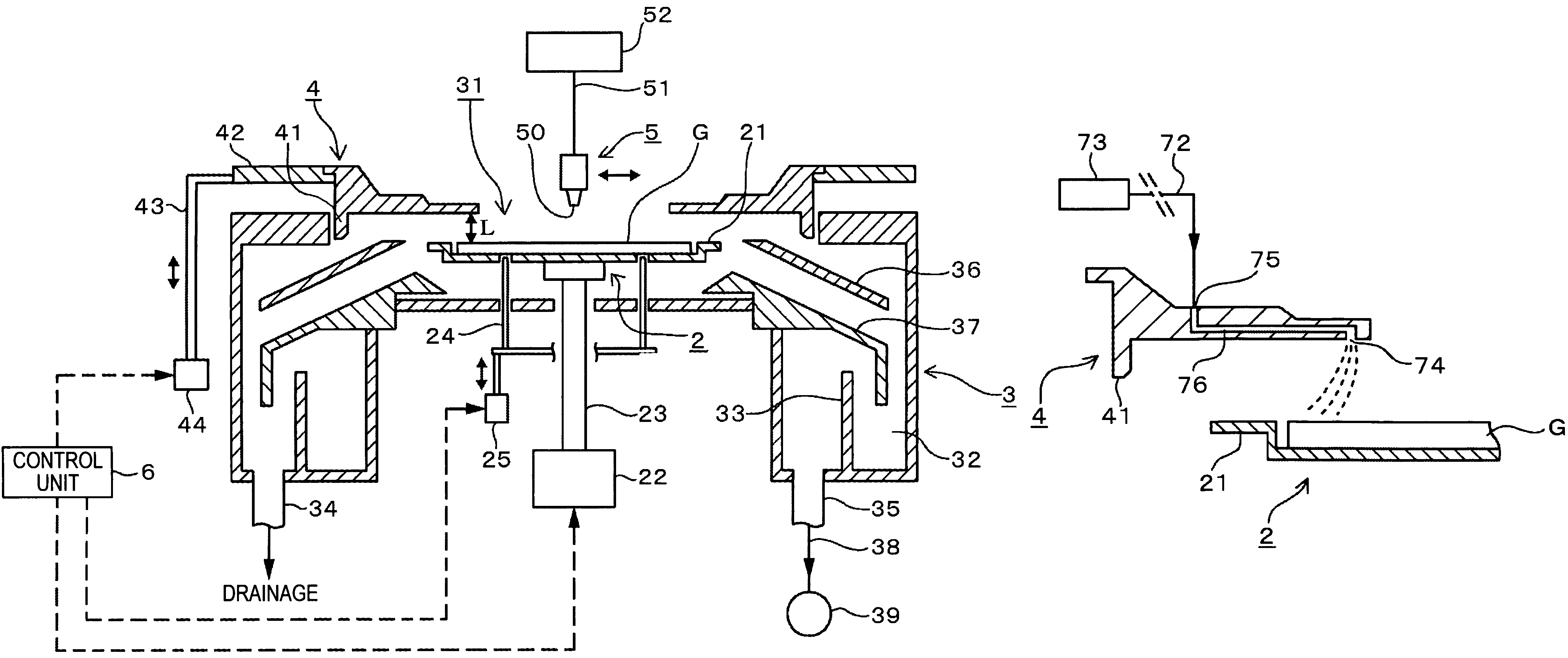
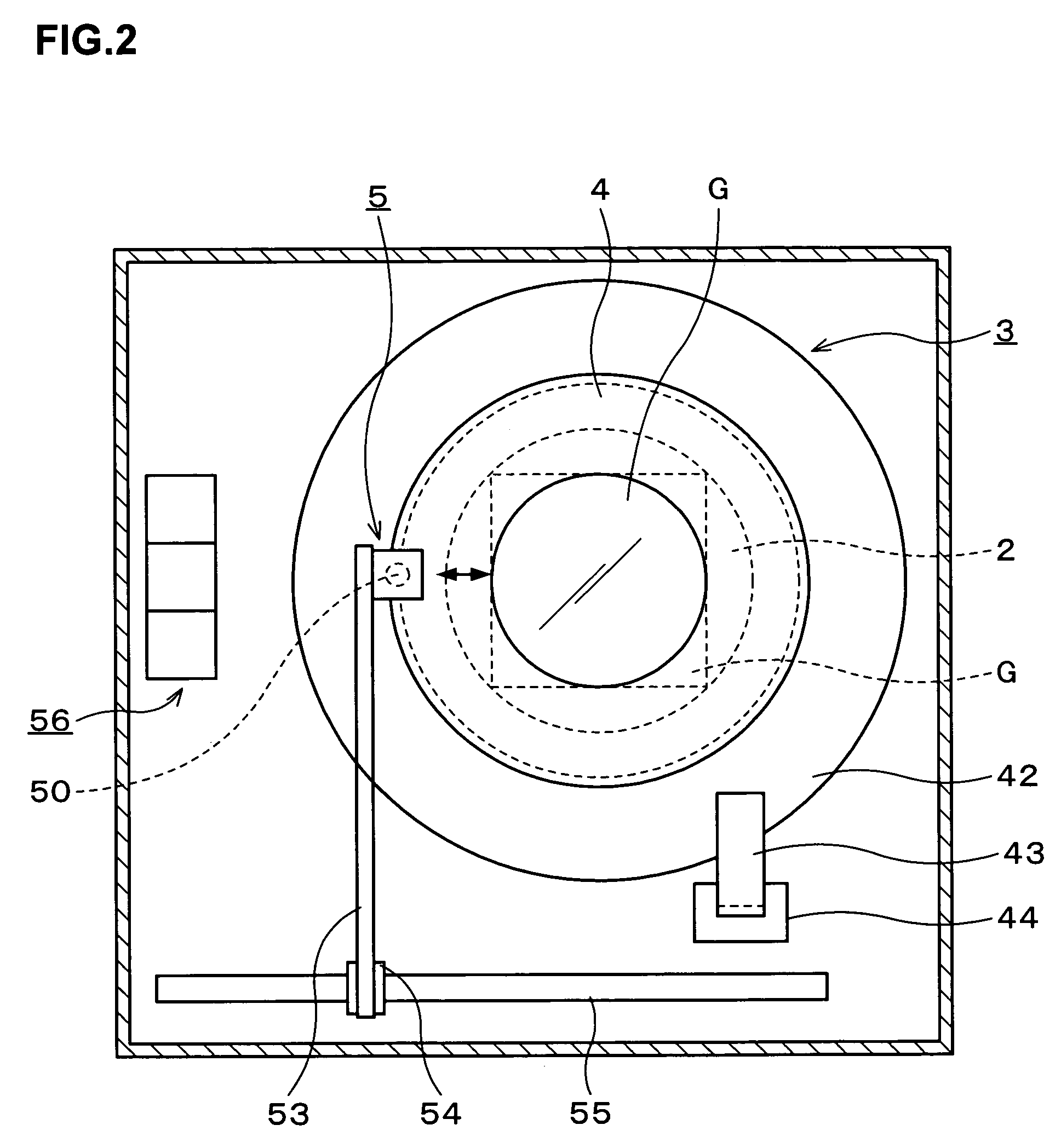
[0041]A coating treatment apparatus according to an embodiment of the present invention will be described with reference to FIG. 1 and FIG. 2. In the drawings, a numeral 2 denotes a spin chuck for horizontally holding a square substrate G, for example, a mask substrate. The spin chuck 2 is provided with a planar portion 21, surrounding the outside of the periphery of the held substrate G such that its outer periphery forms an almost circle looking from above, in such a manner to align in height with, for example, the front face of the substrate G. The spin chuck 2 is connected via a shaft portion 23 with a drive mechanism 22 provided thereunder and configured to freely rotate about the vertical axis and freely rise and lower while holding the substrate G, by means of the drive mechanism 22. Further, the mask substrate is, for example, a glass substrate having a size, for example, 152±0.4 mm in length of a side and 6.35±0.1 mm in thickness.

[0042]The front face of the spin chuck 2 is ...


PUM


Abstract

In the present invention, a gas flow restraining ring facing corner portions of the front face of a substrate horizontally held on a substrate holding unit and movable up and down, is set to a predetermined height in accordance with a coating treatment. Then, a coating solution containing a coating film forming component and a solvent is applied to the front face of the substrate and spread into a thin film state by a so-called spin coating method, and thereafter the substrate is rotated at a high speed so that the coating solution is dried. In this case, it is possible to control fresh gas flow from above the substrate to decrease the difference in evaporation rate of the solvent between the coating solution on the corner portions of the substrate and the coating solution inside them, thus enabling the coating treatment uniform within a plane on the substrate.

Description

BACKGROUND OF THE INVENTION[0001]1. Field of the Invention[0002]The present invention relates to a coating treatment apparatus and a coating treatment method each for applying, into a thin film state, a coating solution containing a coating film forming component and a solvent onto the front face of, for example, a square substrate such as a mask substrate.[0003]2. Description of the Related Art[0004]In a manufacturing process of a semiconductor device and an LCD, processing using a photolithography technique is performed. This processing is performed by a series of steps of applying a predetermined coating solution such as a resist, into a thin film state, onto the front face of, for example, substrates to be processed such as a semiconductor substrate and a mask substrate made of glass and drying it to form a film, and thereafter exposing the substrate to light and then performing developing treatment on the substrate to obtain a desired pattern.[0005]Methods of forming, for examp...

Claims


Application Information

Patent Timeline
Patent Type & Authority Patents(United States)
IPC IPC(8): B05C11/06B05B7/06B05C11/10B05C11/00B05C11/02B05D1/40B05C5/00B05C11/08B05D3/12H01L21/00H01L21/027
CPCH01L21/6715
Inventor HAMADA, MASAHITOHIROTA, FUMIOKOBAYASHI, SHINJI
Owner TOKYO ELECTRON LTD
Why Eureka
Try Eureka