
Spray atomization

a technology of atomization and hydrocarbons, applied in the direction of thermal non-catalytic cracking, other chemical processes, fuels, etc., can solve the problems of difficult contact with many tons of hot, difficult to re-create cracking catalysts with large volumes of heavy oil feed, and difficulty in vaporizing heavier feeds, etc., to achieve the effect of increasing the efficiency of atomization in hydrocarbon processing

Inactive Publication Date: 2009-06-30
BL TECH INC
View PDF12 Cites 1 Cited by
  • Summary
  • Abstract
  • Description
  • Claims
  • Application Information

AI Technical Summary

Benefits of technology

The present invention provides a way to increase the efficiency of atomization in hydrocarbon processing. This is done by creating a water-in-hydrocarbon oil emulsion using a non-ionic surfactant that stabilizes the emulsion. The process involves combining water, fuel oil, and the non-ionic surfactant under specific conditions to form the emulsion. The invention also provides a way to control the atomization of liquid hydrocarbons by combining water, fuel oil, and the non-ionic surfactant and passing them through a spray nozzle to produce controlled hydrocarbon droplet size and distribution.

Problems solved by technology

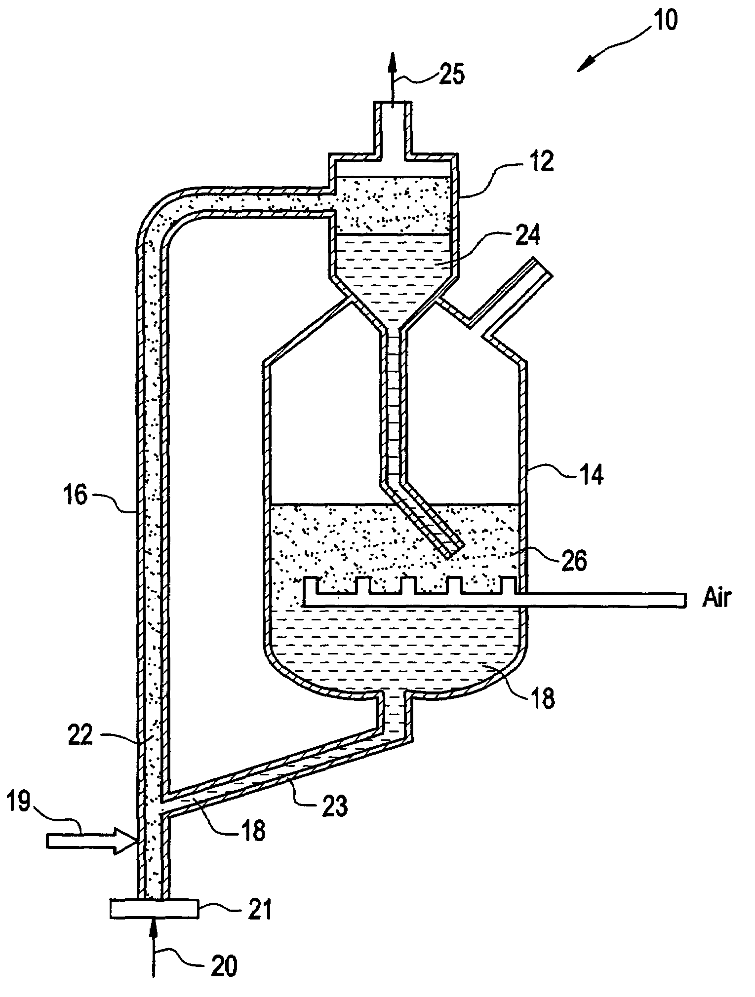
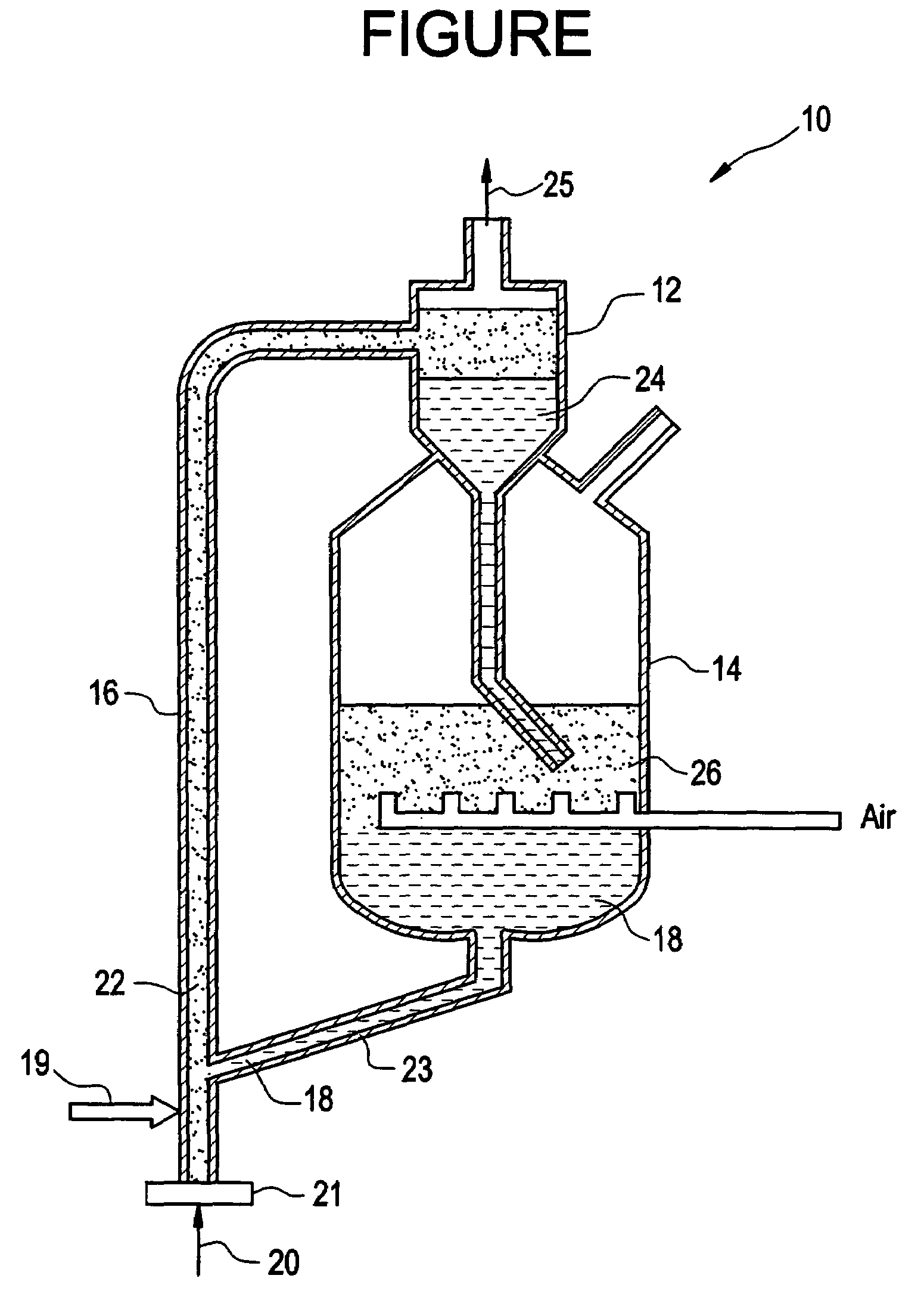
It is known that feed atomization in the base of the FCC riser reactor is a problem in hydrocarbon processing.
In particular, it is difficult to contact many tons per hour of hot, regenerated cracking catalyst with large volumes of heavy oil feed, while ensuring the complete vaporization of the feeds at the bottom of the riser reactor.
Part of this problem can be attributed to the use of heavier feeds in FCC units.
In particular, heavier feeds are more difficult to vaporize because of their high boiling points, and the heavy feeds are harder to atomize because of their high viscosity, even at the high temperatures which exist in FCC riser reactors.
Whereas secondary atomization as a means of improving combustion processes is well established, there has been little, if any, effective transfer of this technology to the hydrocarbon process field.

Method used


Image

  • Spray atomization
  • Spray atomization

Examples


example 1

Determining the Efficacy of Surfactants to Stabilize Water-In-Oil Emulsions

[0037]An experimental vessel was constructed in order test the ability of various surfactants to stabilize water-in-oil emulsions. The experimental vessel was of a pipe construction that allowed the experiment to be conducted under appropriate temperature and pressure conditions that reproduced those typically encountered in hydrocarbon processing. The experimental vessel was equipped with a base that included a blender blade for generating emulsions, and with feed-throughs on the top that allowed for removal of aliquots of process fluid for microscopic examination. The fluid shears experienced in the atomization nozzle were simulated by the turbulence created by the blender blades. A speed-controlled motor system was used to control this turbulence. The top of the sample vessel included a provision for a pressure transducer, an internal temperature transducer, and a dip tube system which allowed for removal ...


PUM

PropertyMeasurementUnit
temperaturesaaaaaaaaaa
diameteraaaaaaaaaa
operating temperaturesaaaaaaaaaa

Abstract

The present invention provides a feedstock composition for increasing the efficiency of atomization in hydrocarbon processing that includes a water-in-hydrocarbon oil emulsion including a non-ionic surfactant capable of stabilizing the emulsion and having a hydrophilic-lipophilic balance of greater than about 12. The emulsion includes water droplets of about 5 to about 10 microns in diameter, the droplets being dispersed substantially uniformly in the hydrocarbon oil phase. These surfactants are capable of stabilizing the water-in-hydrocarbon oil emulsion under relevant temperature and pressure conditions for hydrocarbon processing. The inventive feedstock composition provides a metastable water-in-oil emulsion where expanding water vapor explodes under spray conditions where the system pressure is released, demolishing a larger oil droplet and producing smaller oil droplets.

Description

FIELD OF THE INVENTION[0001]The invention relates to a hydrocarbon feedstock composition suitable to be handled in a pressure-type atomizer. In particular, the invention relates to a feedstock composition for improving atomization in hydrocarbon processing that includes an emulsified water-in-hydrocarbon oil emulsion.BACKGROUND OF THE INVENTION[0002]Catalytic cracking involves the processing of gas oils using catalysts to crack the carbon-carbon bonds. In particular, catalytic cracking consists of breaking saturated C12+molecules into C2-C4 olefins and paraffins, gasoline, light oil, and coke. Cracking serves to lower the average molecular weight and to produce higher yields of fuel products. The majority of the reactions are endothermic and heat must be supplied to the cracking process. Cracking can be either purely thermal or thermal and catalytic. In general, it is desirable to promote catalytic cracking over thermal cracking since thermal cracking produces unwanted by-products.[...

Claims


Application Information

Patent Timeline
Patent Type & Authority Patents(United States)
IPC IPC(8): B01F3/08C10G11/18C10G9/36C10L1/32
CPCC10L1/328C10G11/18C10L1/32
Inventor PARKER, WILEY L.CROSS, COLLIN W.GOLIASZEWSKI, ALAN E.
Owner BL TECH INC
Learn More